
Hybrid power automobile gearbox unit cooling system and cooling method

A cooling system and transmission technology, applied in transmission components, gear lubrication/cooling, transmission parts, etc., can solve the problem of inability to meet the precise cooling requirements of the transmission of hybrid electric vehicles, the oil temperature cannot quickly reach the suitable temperature of the transmission, and the speed change The efficiency of the box and its coupling mechanism is low, so as to ensure the cooling quality and efficiency, improve the cooling effect, and achieve the effect of rapid oil pressure

Active Publication Date: 2015-01-14
奇瑞控股集团有限公司
View PDF5 Cites 24 Cited by
  • Summary
  • Abstract
  • Description
  • Claims
  • Application Information

AI Technical Summary

Problems solved by technology

[0002] At present, the traditional automotive gearbox cooling technology mostly adopts single air cooling or water cooling, which is easy to over-cool the oil temperature under idling conditions, causing the oil temperature to fail to reach the appropriate temperature of the gearbox quickly, resulting in additional loss of power, and at the same time Existing gearbox single cooling technology cannot achieve precise cooling control, and cannot accurately control cooling under high-torque conditions, resulting in defects such as low efficiency of the gearbox and its coupling mechanism, and insufficient performance improvement
For the cooling technology of hybrid vehicle transmission, the single cooling method of traditional transmission is generally used, which cannot meet the precise cooling requirements of hybrid vehicle transmission, and in terms of energy saving and emission reduction, a new type of cooling system is required to be applied to hybrid vehicles. on the gearbox unit

Method used


Image

  • Hybrid power automobile gearbox unit cooling system and cooling method
  • Hybrid power automobile gearbox unit cooling system and cooling method
  • Hybrid power automobile gearbox unit cooling system and cooling method

Examples


Embodiment Construction

[0027] The technical solutions of the present invention will be described in detail below in conjunction with the accompanying drawings, so that those skilled in the art can understand the present invention more clearly, but the protection scope of the present invention is not limited thereby.

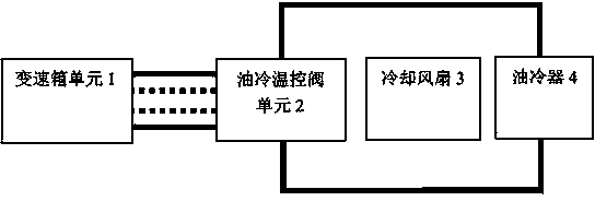
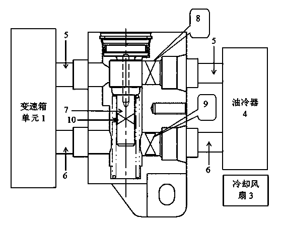
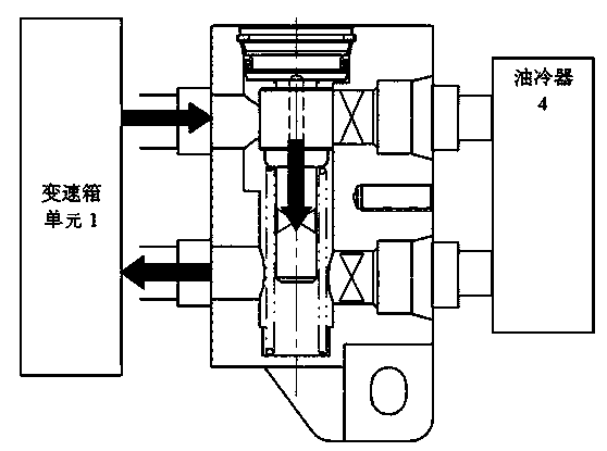
[0028] first combined with figure 1 Illustrate the basic working principle of the present invention, as attached figure 1 As shown, the transmission unit cooling system of the present invention as a whole includes a transmission unit 1, an oil cooling temperature control valve unit 2, an oil cooler 4 and a cooling fan 3, and the oil inlet and outlet of the transmission unit 1 are connected In the oil cooling temperature control valve unit 2, the oil from the gearbox unit flows into the oil cooling temperature control valve unit 2. There is a return flow path inside the oil cooling temperature control valve unit 2. At the same time, the oil cooling temperature control valve unit 2 and t...


PUM


Abstract

The invention provides a hybrid power automobile gearbox unit cooling system and cooling method. An oil incoming pipe, an oil discharging pipe and a returning pipe communicating the oil incoming pipe and the oil discharging pipe are arranged in an oil cooling temperature control valve unit, the oil temperature sensing information of a gearbox unit is combined, and valves of oil pipes are controlled to open and close dynamically; on the idling condition, oil from the gearbox unit flows back to the gearbox from the oil cooling temperature control valve unit directly, time for the oil flowing back the gearbox is shortened, oil pressure can be established rapidly, and the gearbox and a coupled mechanism thereof operate at the proper temperature rapidly; when an engine operates in high speed and the gearbox is under high load, oil friction heat is increased sharply, oil of the gearbox flows to an oil cooler completely through the oil cooling temperature control valve, waste heat is radiated through the oil cooler, and the coil flows back to the gearbox unit, so that the accurate control of the oil temperature of the gearbox is implemented, friction loss, oil consumption and discharging are reduced, service life of the gearbox unit is prolonged, and shift quality is guaranteed.

Description

technical field [0001] The invention relates to a cooling technology of a gearbox, in particular to a cooling system and a cooling method of a gearbox unit of a hybrid electric vehicle. Background technique [0002] At present, the traditional automotive gearbox cooling technology mostly adopts single air cooling or water cooling, which is easy to over-cool the oil temperature under idling conditions, causing the oil temperature to fail to reach the appropriate temperature of the gearbox quickly, resulting in additional loss of power, and at the same time The existing gearbox single cooling technology cannot achieve precise cooling control, and cannot accurately control cooling under high torque conditions, resulting in defects such as low efficiency of the gearbox and its coupling mechanism, and insufficient performance improvement. For the cooling technology of hybrid vehicle transmission, the single cooling method of traditional transmission is generally used, which canno...

Claims


Application Information

Patent Timeline
IPC IPC(8): F16H57/04
CPCF16H57/0412F16H2700/00
Inventor 周定华程静赵夕长马连功赵子明
Owner 奇瑞控股集团有限公司
Learn More