
Pneumatic launcher with novel gas way system

A gas circuit system and transmitter technology, which is applied in the field of pneumatic transmitters, can solve the problems that can only be used in fixed places such as laboratories, the kinetic energy of the muzzle cannot be kept constant, and there is no continuous firing for multiple times, so as to simplify the gas circuit. Design, structure layout compact, low weight effect

Active Publication Date: 2015-01-07
GENERAL ENG RES INST CHINA ACAD OF ENG PHYSICS
View PDF7 Cites 11 Cited by
  • Summary
  • Abstract
  • Description
  • Claims
  • Application Information

AI Technical Summary

Problems solved by technology

Traditional pneumatic launchers mainly include gas cannons, air guns, life-saving throwers, etc. Among them, the gas cannon is a test device that can accelerate the load to a very high speed, but the system is large in size and weight, and generally can only be used in the laboratory. and other fixed occasions; the air gun is a portable pneumatic launcher, but the launch load is small, and as the pressure of the gas cylinder drops, the kinetic energy of the muzzle generally cannot remain constant; the life-saving thrower is a widely used life-saving equipment. The launch load and distance are between air guns and gas cannons, but a set of life-saving throwers can only be fired once after being inflated, and generally do not have the ability to launch multiple times continuously

Method used


Image

  • Pneumatic launcher with novel gas way system

Examples


Embodiment Construction

[0017] In order to make the technical means, creative features, goals and effects achieved by the present invention easy to understand, the present invention will be further described below in conjunction with specific embodiments.

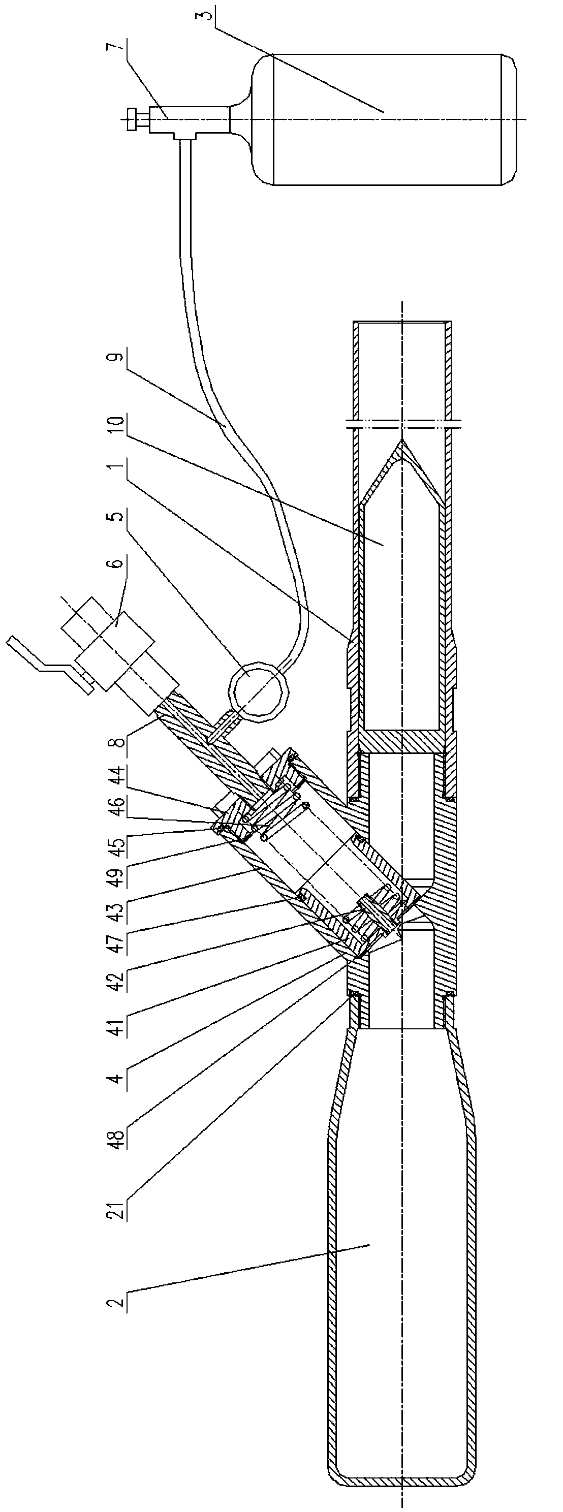
[0018] Such as figure 1 As shown, it shows a pneumatic launcher with a new gas path system of the present invention, including a gun barrel 1, an air chamber 2, a control device located in the middle of the connection between the gun barrel 1 and the gas chamber 2, and connected to the control device The high-pressure gas cylinder 3 and the projectile 10 installed in the barrel 1, the control device includes the pneumatic quick-opening valve 4 connecting the barrel 1 and the air chamber 2, the tee 8 installed on the pneumatic quick-opening valve 4, and the The launch valve 6 on the tee 8 and the decompression valve 5 installed on the tee 8 are all provided with sealing gaskets 21 between the pneumatic quick opening valve 4 and the gun barrel 1 and...


PUM


Abstract

The invention discloses a pneumatic launcher with a novel gas way system. The pneumatic launcher comprises a gun barrel, a gas chamber, a control device, a high-pressure gas bottle and a projectile, the control device comprises a pneumatic quick-opening valve connecting the gun barrel with the gas chamber, a three-way joint mounted on the pneumatic quick-opening valve, a launching valve mounted on the three-way joint, and a pressure reducing valve, and an inflation valve is mounted on the high-pressure gas bottle and connected with the pressure reducing valve through a hose. When the high-pressure gas bottle inflates the gas chamber, the pneumatic quick-opening valve and the launching valve are closed, and after the inflation valve is opened, high-pressure gas in the high-pressure gas bottle enters the gas chamber; when pressure in the pneumatic quick-opening valve reaches preset pressure, the pressure reducing valve is automatically closed; during launching, the inflation valve is closed firstly, the launching valve is opened secondly, high-pressure gas in the pneumatic quick-opening valve is quickly released, a valve core is quickly opened under drive of pressure of the gas chamber, and the high-pressure gas in the gas chamber quickly enters the gun barrel through a valve port and drives the projectile to be launched. The pneumatic launcher is simple in structure, controllable in gas pressure, adjustable in launching distance, large in launching load and high in launching efficiency.

Description

technical field [0001] The invention relates to a pneumatic launcher with a novel gas path system, in particular to a pneumatic launcher which can be used to launch fire-fighting bombs, anti-riot bombs and life-saving equipment. Background technique [0002] The working principle of the pneumatic launcher is to accelerate the load to a certain speed and launch through the rapid release of compressed gas. Traditional pneumatic launchers mainly include gas cannons, air guns, life-saving throwers, etc. Among them, the gas cannon is a test device that can accelerate the load to a very high speed, but the system is large in size and weight, and generally can only be used in the laboratory. and other fixed occasions; the air gun is a portable pneumatic launcher, but the launch load is small, and as the pressure of the gas cylinder drops, the kinetic energy of the muzzle generally cannot remain constant; the life-saving thrower is a widely used life-saving equipment. The launch lo...

Claims


Application Information

Patent Timeline
IPC IPC(8): F41B11/80B63C9/26
Inventor 李锋朱永清张映梅卢永刚
Owner GENERAL ENG RES INST CHINA ACAD OF ENG PHYSICS
Learn More