Optical fiber grating pulse diagnosis sensor probe and dense array fiber optic pulse diagnosis instrument

A sensor probe and fiber grating technology, applied in the direction of sensors, using spectrum diagnosis, diagnosis, etc., can solve the problems that the sensor cannot be pressed and placed correctly, the sensor probe is large in size, the sensor structure is complex, etc., to simplify the production and assembly process, signal-to-noise High ratio, low noise effect

Active Publication Date: 2017-01-11
济宁高新科达科技项目服务有限公司
View PDF1 Cites 0 Cited by
  • Summary
  • Abstract
  • Description
  • Claims
  • Application Information

AI Technical Summary

Problems solved by technology

However, the structure of the sensor is complex, cumbersome, and bulky, especially when multiple sensors are coaxial when forming an array, so it is only suitable for a 1XN sensor array; in addition, since each sensor shares the same axis, the sensors affect each other; In this structure, the fiber grating is placed parallel to the wrist of the human body. Although the fiber diameter is 125um, the length is more than 1cm, so this method will inevitably result in a larger sensor probe; It needs to pass through multiple transmission shaft components, resulting in serious information loss
[0004] The blood vessels in the human wrist are distributed in a tubular shape with a diameter of about 3 mm, and are often hidden between the tendons on both sides. If the sensor probe is too large, the sensor will not be able to be properly pressed on the blood vessels

Method used


Image

  • Optical fiber grating pulse diagnosis sensor probe and dense array fiber optic pulse diagnosis instrument
  • Optical fiber grating pulse diagnosis sensor probe and dense array fiber optic pulse diagnosis instrument
  • Optical fiber grating pulse diagnosis sensor probe and dense array fiber optic pulse diagnosis instrument

Examples


Embodiment 2

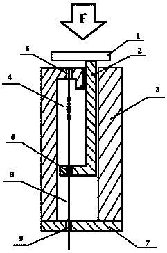
[0059] A dense array optical fiber pulse diagnosis instrument for pulse measurement and information collection, it includes a broadband light source 13 connected together with an optical circulator 14, a grating demodulator 18 and an optical fiber coupler 15, the broadband light source 13 sends out The spectrum reaches the fiber coupler 15 through the optical circulator 14, and each fiber branch branched out by the fiber coupler 15 is respectively connected to the pigtail 8 of each sensing unit fiber grating 4 on the fiber grating pulse diagnosis sensor probe 17, The optical signal returned from the fiber grating pulse diagnosis sensor probe 17 returns to the optical circulator 14 through the fiber coupler 15, and then enters the grating demodulator 18 for demodulation. The structure of the fiber grating pulse diagnosis sensor probe 17 is the same as that of Embodiment 1 and will not be repeated here.

[0060] The fiber coupler 15 is a 1×6 fiber coupler. 6 optical fibers are ...


PUM


Abstract

A FBG (Fiber Bragg Grating) pulse-taking sensor probe comprises a casing and at least a sensing unit which is arranged inside the casing; the sending unit comprises a sensing unit outer casing which is in a hollow pipe shape; one end of the sensing unit outer casing is closed; the top of the sensing unit outer casing is provided with a top cover; a first optical fiber fixing hole and a guiding hole which plays a role in guiding route are formed in the top cover; an L-shaped pull rod is arranged inside the sensing unit outer casing; the L-shaped pull rod comprises a cross arm and a longitudinal arm; the longitudinal arm is matched with the guiding hole and the upper portion of the longitudinal arm penetrates the guiding hole to be matched with the guiding hole in a sliding mode; a second optical fiber fixing hole is formed in the cross arm; a tail fiber outlet hole is formed in a sealing bottom; one end of the FBG is fixed inside the first optical fiber fixing hole and the other end is fixed inside the second optical fiber fixing hole; a tail fiber of the FBG penetrates the tail fiber outlet hole to extend out of the sending unit. According to an intensive array type optical fiber pulse-taking instrument, an optical signal returned from the FBG pulse-taking sensor probe returns to an optical circulator through an optical fiber coupler and then enters into an optical grating demodulation instrument to be demodulated.

Description

technical field [0001] The present application relates to an optical fiber pulse diagnosis sensor, in particular to a dense array optical fiber pulse diagnosis sensor probe for pulse measurement and information collection. Background technique [0002] Pulse pulse is one of the ancient medical techniques that have been passed down for thousands of years in our country. Through the fluctuation and vibration information of the pulse, the health status of the human body can be obtained, and some diseases can also be diagnosed. However, traditional Chinese medicine relies entirely on the doctor's fingertips and lacks objective analysis and evidence. This has also caused traditional Chinese medicine to not be recognized by Western countries and other parts of the world, and has seriously hindered the progress of Chinese medicine technology in my country. [0003] In recent years, with the progress of my country's technology and the open mind of medical workers, they have graduall...

Claims


Application Information

Patent Timeline
Patent Type & Authority Patents(China)
IPC IPC(8): A61B5/02
CPCA61B5/0075A61B5/02A61B5/6824
Inventor 倪家升王昌金伟李淑娟王英英张雪君辛超张发祥翟瑞占
Owner 济宁高新科达科技项目服务有限公司
Why Eureka
Try Eureka