


Quick Research
Generate reliable direction feasibility study reports for your R&D in just a few steps.

Technical Q&A
Discover and master advanced knowledge NOW. Basics, ideas, possibilities, all at once.

Find Solutions
As an expert in R&D theories, this can generate solutions to your technical problems instantly.

Evaluate Feasibility
Analyze your overall solution with one click, know your potential R&D risks in advance.

Monitor Landscape
Get weekly tech updates, stay abreast of the latest tech innovations and key insights.
Liquid cooling heat dissipation device and liquid cooling heat dissipation equipment
A liquid cooling and equipment technology, applied in the direction of instruments, electrical digital data processing, digital data processing parts, etc., can solve the problems of inconvenient disassembly and installation
- Summary
- Abstract
- Description
- Claims
- Application Information
AI Technical Summary
Problems solved by technology
Method used
Image

Examples
Embodiment 1
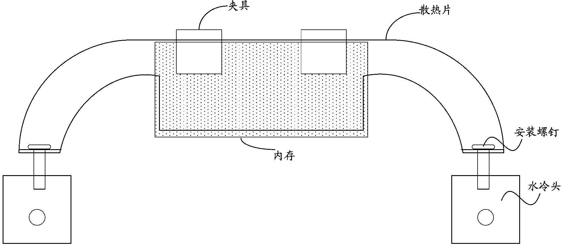
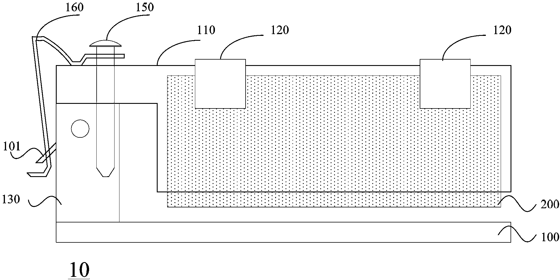
[0056] Figure 2A It is an application schematic diagram of a liquid cooling heat dissipation device provided by Embodiment 1 of the present invention. The device provided by this embodiment is suitable for heat dissipation of memory. Such as Figure 2A As shown, the liquid cooling heat dissipation device 10 includes: a first heat sink 110, a second heat sink 111 ( Figure 2A not shown in ), clamp 120, water cooling head 130 and fixing parts of water cooling head 130; fixing parts of water cooling head 130 include fixing rod 150, buckle 160 and hook 101; , for placing in parallel on both sides of the memory 200 respectively, and contacting with both sides of the memory 200; clamp 140, for placing the first heat sink 110 and the second heat sink 111 placed on both sides of the memory 200 with the memory 200 Fixed; the water cooling head 130 is used to be fixed on the motherboard 100, and when the first heat sink 110 and the second heat sink 111 are respectively placed in par...
Embodiment 2
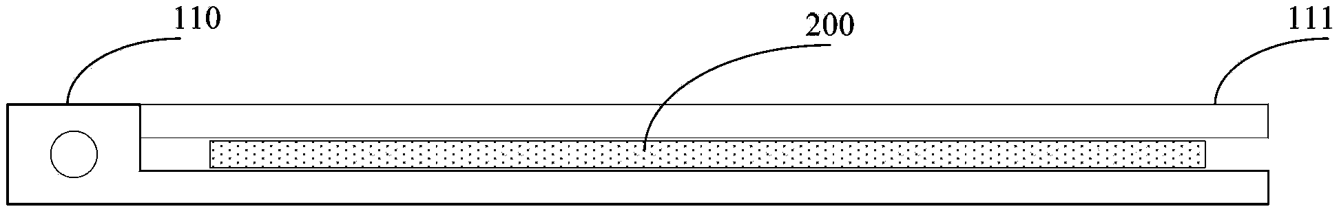
[0064] Figure 2A It can also be used as an application schematic diagram of a liquid cooling heat dissipation device provided in Embodiment 2 of the present invention, Figure 3A It is a top view of a heat sink in a liquid-cooled heat dissipation device provided in Embodiment 2 of the present invention, Figure 3B It is a side view of a heat sink in a liquid cooling heat dissipation device provided by Embodiment 2 of the present invention. In the liquid cooling heat dissipation device 10 provided in this embodiment, different from the above embodiments, the part of the second heat sink 111 extending from one end of the memory 200 is used for contacting the first heat sink 110 and the water cooling head 130 part of the top contact, the second cooling fin 111 is provided with a through hole extending from one end of the memory 200; 110 and the second heat sink 111 are inserted into the holes of the water cooling head 130 . It should be noted that, in this embodiment, the hoo...
Embodiment 3
[0068] Figure 4 It is an application schematic diagram of a liquid cooling heat dissipation device provided by Embodiment 3 of the present invention. On the basis of the liquid cooling heat dissipation device provided in the above embodiments, the liquid cooling heat dissipation device 10 provided in this embodiment, the fixing part of the water cooling head 130 also includes a support frame 170, and the support frame 170 is provided with holes. The hole is a through hole, and the hook 101 is arranged on the outer wall of the support frame 170; the support frame 170 is used to fix on the main board 100 and support the water cooling head 130, so that the water cooling head 130 is fixed on the main board 100 through the support frame 170 The other end of the fixing rod 150 is also used to pass through the through hole of the water cooling head 130 and insert into the hole of the support frame 170 .
[0069]In the liquid cooling heat dissipation device 10 provided in this embod...
PUM
 Abstract
Description
Claims
Application Information
 - R&D Engineer
- R&D Manager
- IP Professional
- Industry Leading Data Capabilities
- Powerful AI technology
- Patent DNA Extraction
Browse by: Latest US Patents, China's latest patents, Technical Efficacy Thesaurus, Application Domain, Technology Topic, Popular Technical Reports.
© 2024 PatSnap. All rights reserved.Legal|Privacy policy|Modern Slavery Act Transparency Statement|Sitemap|About US| Contact US: help@patsnap.com