
A method and device for controlling the impedance continuity of a transmission line on a pcb

A transmission line and continuity technology, which is applied in printed circuit manufacturing, electrical components, printed circuits, etc., can solve the problems of unstable signal reception, inability to effectively reduce the impact of impedance mutation, and affect signal quality, so as to avoid impedance mutation Effect

Active Publication Date: 2017-04-12
INSPUR BEIJING ELECTRONICS INFORMATION IND
View PDF6 Cites 1 Cited by
  • Summary
  • Abstract
  • Description
  • Claims
  • Application Information

AI Technical Summary

Problems solved by technology

However, this method cannot effectively reduce the impact of impedance mutations because it can only offset part of the reflection noise
In particular, when the data rate of the signal transmitted on the transmission line is further increased, for example, when the data rate is increased to 20Gpbs, the reflection noise will obviously affect the quality of the signal, and even cause the signal to not be received stably

Method used


Image

  • A method and device for controlling the impedance continuity of a transmission line on a pcb
  • A method and device for controlling the impedance continuity of a transmission line on a pcb
  • A method and device for controlling the impedance continuity of a transmission line on a pcb

Examples


Embodiment Construction

[0052] In order to make the object, technical solution and advantages of the present invention clearer, the process of the embodiments of the present invention will be described in detail below in conjunction with the accompanying drawings. It should be noted that, in the case of no conflict, the embodiments in the present application and the features in the embodiments can be combined arbitrarily with each other.

[0053] The steps shown in the flowcharts of the figures may be performed in a computer system, such as a set of computer-executable instructions. Also, although a logical order is shown in the flowcharts, in some cases the steps shown or described may be performed in an order different from that shown or described herein.

[0054] The impedance standard in this article refers to the corresponding impedance standard of the transmission line unless otherwise stated. The transmission line herein refers to a transmission line composed of a wide part of the transmissio...


PUM


Abstract

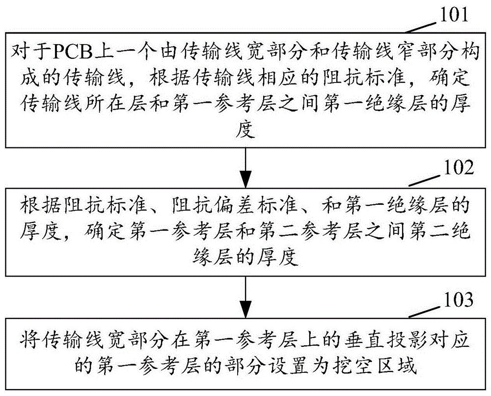
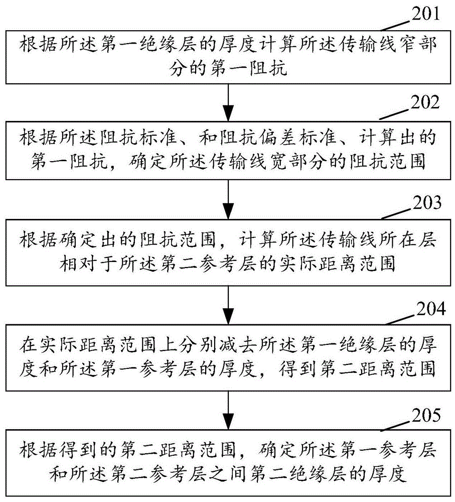
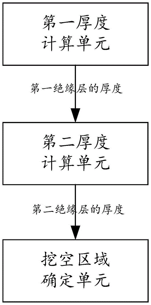
The invention discloses a method and a device for controlling impedance continuity of a transmission line on a PCB (printed circuit board). The method includes: for the transmission line, composed of a wide portion and a narrow portion, on the PCB, determining thickness of a first insulating layer between a PCB layer where the transmission line is positioned and a first reference layer according to predetermined corresponding impedance standard of the transmission line; determining thickness of a second insulating layer between the first reference layer and the second reference layer according to the impedance standard, predetermined impedance deviation standard and the thickness of the first insulating layer; setting a portion, corresponding to vertical projection of the wide portion of the transmission line on the first reference layer, of the first reference layer to be a hollow area. By the technical scheme, adjusting of impedance of the narrow portion and the wide portion of the transmission line under the circumstance that line width of the transmission line changes to meet the impedance deviation standard is realized, so that sudden change of impedance of the transmission line is avoided.

Description

technical field [0001] The invention relates to a printed circuit board (PCB) design technology, in particular to a method and a device for controlling the impedance continuity of a transmission line on a PCB in PCB design. Background technique [0002] In PCB design, such a situation is often encountered during PCB wiring. For the transmission line on the top and bottom layers of the PCB, that is, the microstrip line, when passing through an area with limited wiring space, in order to improve the utilization of the wiring space in this area, The width of the transmission line needs to be reduced. That is to say, when wiring the PCB, it is sometimes necessary to change the width of the transmission line. [0003] The change in the width of the transmission line leads to the discontinuity of the impedance of the transmission line, that is to say, the impedance of the narrow part of the transmission line is inconsistent with that of the wide part of the transmission line. In ...

Claims


Application Information

Patent Timeline
Patent Type & Authority Patents(China)
IPC IPC(8): H05K3/00
Inventor 宗艳艳
Owner INSPUR BEIJING ELECTRONICS INFORMATION IND
Learn More