
Molding sand drum dryer

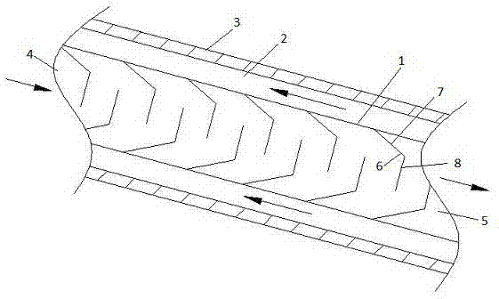
A drum dryer and drum technology, applied in the field of machinery, can solve the problems of increasing electric energy, resources, waste of funds, increasing the cost of drum rolling power, etc., and achieve the effects of improving gas drying, stabilizing drying capacity, and increasing temperature

Inactive Publication Date: 2014-12-24
赵勇辉
View PDF4 Cites 5 Cited by
  • Summary
  • Abstract
  • Description
  • Claims
  • Application Information

AI Technical Summary

Problems solved by technology

[0015] 1. Driving the drum to rotate through the transmission structure requires a large amount of industrial electricity consumption, which is a waste of electricity, which does not conform to the concept of environmental protection and energy saving. At the same time, it is also a waste of resources and funds for users;
[0016] 2. The materials to be dried are scattered in the drum and turned over in the drum following the rotation of the drum, which may easily cause partial drying and uneven drying;
[0017] 3. There is a crushing device for the material to be dried inside the drum, the internal structure is complex, and it is difficult to maintain after being damaged;
[0018] 4. Since the drum has to withstand the impact of the material to be dried, the ability of the drum to withstand the impact must be strong enough. Therefore, the quality of the drum is high, and the production cost and materials are high. After the material cost is increased, the quality of the drum will decrease. Increase, increase the power consumption of the drum, increase the power used
[0019] 5. The material to be dried will be rolled out quickly in the drum. It is necessary to prolong the drying time by extending the length of the dryer, increasing the floor area and the capital cost of the equipment, and will inevitably increase the power cost of the drum rolling, as well as the equipment. The repair cost and maintenance costs

Method used


Image

  • Molding sand drum dryer

Examples


Embodiment Construction

[0032] The present invention will be further explained below in conjunction with the accompanying drawings and specific embodiments. It should be understood that the following specific embodiments are only used to illustrate the present invention but not to limit the scope of the present invention. It should be noted that the words "front", "rear", "left", "right", "upper" and "lower" used in the following description refer to the directions in the drawings, and the words "inner" and "outer ” refer to directions towards or away from the geometric center of a particular part, respectively.

[0033] The present invention is described in further detail now in conjunction with accompanying drawing. These drawings are all simplified schematic diagrams, which only illustrate the basic structure of the present invention in a schematic manner, so they only show the configurations related to the present invention.

[0034] The direction of the arrow in the accompanying drawings repre...


PUM


Abstract

The invention relates to a molding sand drum dryer. The molding sand drum dryer comprises a drum, wherein the drum is obliquely arranged relative to the horizontal plane, the upper end of the drum is a feed end, the lower end of the drum is a discharge end, a baffle which is spirally coiled from the feed end to the discharge end is arranged on the inner wall of the drum, the baffle comprises an inclined section and a perpendicular section, and the perpendicular section is perpendicular to the drum. A steam pipe is arranged on the surface of the drum, a gap is reserved between the steam pipe and the outer surface of the drum, one end of the steam pipe is connected with a hot air supply system and is close to the feed end of the drum, the other end of the steam pipe is connected with a hot air recovery system and is close to the discharge end of the drum, the feed end of the drum is connected with the hot air supply system and the discharge end of the drum is connected with the hot air recovery system. The molding sand drum dryer can guarantee more stable drying environment and drying efficiency and can guarantee molding sand drying uniformity and consistency.

Description

technical field [0001] The invention relates to a drum dryer for molding sand, which is a drum dryer capable of increasing the passing path of the molding sand in the drum and prolonging the residence time, belonging to the mechanical field. Background technique [0002] Molding sand is a material used for modeling in casting. Molding sand is generally made by mixing molding materials such as raw sand for casting, molding sand binder and auxiliary additives in a certain proportion. Molding sand can be divided into clay sand, water glass sand, cement sand, resin sand, etc. according to the different binders used. Clay sand, water glass sand and resin sand are the most used. [0003] The role of molding sand in foundry production is extremely important, and the casting waste caused by poor quality of molding sand accounts for about 30-50% of the total casting waste. [0004] The usual requirements for molding sand are: ① High strength and thermal stability to withstand vari...

Claims


Application Information

Patent Timeline
Patent Type & Authority Applications(China)
IPC IPC(8): F26B11/04F26B23/10F26B25/08
Inventor 陈凌王琰任琪程晓
Owner 赵勇辉
Learn More