A high temperature resistant vibration tool for horizontal wells

A vibrating tool and high-temperature-resistant technology, which is applied to vibration generating devices, wellbore/well components, earthwork drilling and production, etc., can solve problems such as self-locking of coiled tubing, inability to successfully complete drilling operations, and impact on service life, so as to improve work efficiency. Reliability, convenience for large-displacement operations, and improved high-temperature resistance

Active Publication Date: 2017-10-20
JEREH ENERGY SERVICES
View PDF1 Cites 0 Cited by
  • Summary
  • Abstract
  • Description
  • Claims
  • Application Information

AI Technical Summary

Problems solved by technology

However, limited by the coiled tubing itself, the coiled tubing is prone to self-locking in large horizontal wells, causing the coiled tubing to fail to reach the predetermined depth for related operations, or to fail to apply sufficient drilling pressure after reaching the designated position, resulting in failure of the coiled tubing operation. Unable to successfully complete relevant drilling operations
The published patent "Vibration Tool for Extended Reach Well" Patent No.: CN 202673216U, although the torque friction of the drill pipe has been reduced, which is beneficial to the construction of underground operations, but there are still the following deficiencies: First, the motor is used as the vibration power. Obstruction of the passage restricts the displacement of the coiled tubing, making it impossible to carry out large-displacement operations; second, the motor structure contains rubber parts, which cannot be used for a long time in high-temperature wells and geothermal wells, and the service life is greatly affected; It uses the connection structure of cardan shaft, transmission shaft and accelerator, etc., and its connection structure is easy to wear in high-frequency and high-temperature operations, which will affect the service life

Method used


Image

  • A high temperature resistant vibration tool for horizontal wells
  • A high temperature resistant vibration tool for horizontal wells
  • A high temperature resistant vibration tool for horizontal wells

Examples


Embodiment Construction

[0025] The principles and features of the present invention are described below in conjunction with the accompanying drawings, and the examples given are only used to explain the present invention, and are not intended to limit the scope of the present invention.

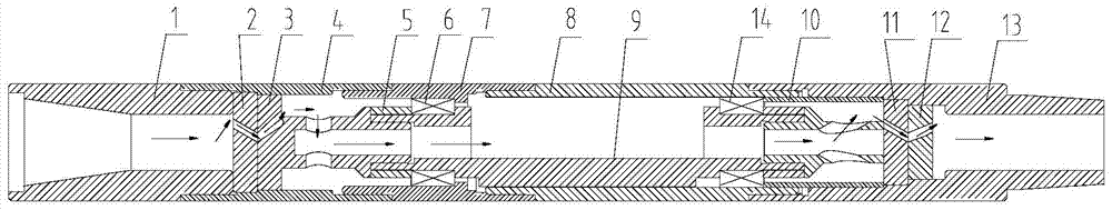
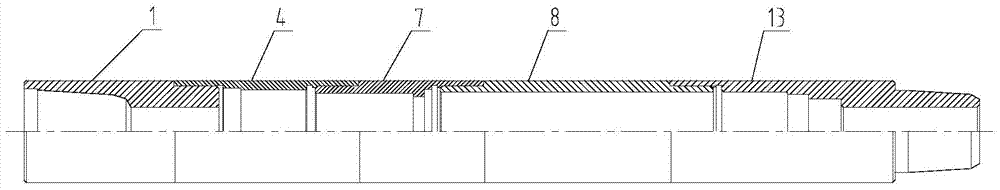
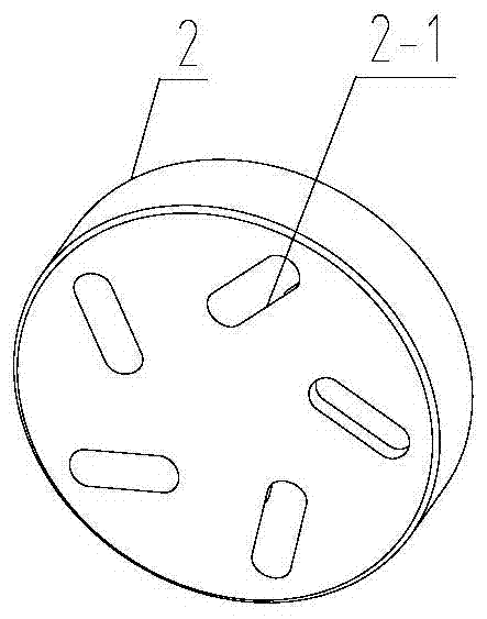
[0026] Such as Figure 1 to Figure 6 As shown, a high-temperature-resistant vibration tool for horizontal wells includes a housing assembly and a vibration assembly located inside the housing assembly:

[0027] The shell assembly includes an upper joint 1, an upper joint sleeve 4, a connecting sleeve 7, an outer sleeve 8 and a lower joint 13 which are sequentially socketed from top to bottom; the vibration assembly includes an upper turbine 3, which is sequentially connected from top to bottom. The eccentric shaft 9 and the lower end turbine 11, the vibration assembly is installed in the housing assembly through the upper end bearing 6 and the lower end bearing 14, and the upper end bearing 6 and the lower end beari...


PUM


Abstract

The invention relates to a high-temperature-resistant vibrating tool for horizontal wells, comprising a shell assembly and a vibrating assembly arranged inside the shell assembly, characterized in that: the shell assembly includes sequentially socketed from top to bottom The upper joint, the upper joint sleeve, the connecting sleeve, the jacket and the lower joint; the vibration assembly includes the upper turbine, the eccentric shaft and the lower turbine connected sequentially from top to bottom, and the vibration assembly is installed on the In the housing assembly, the upper end bearing and the lower end bearing are respectively sleeved on the two ends of the eccentric shaft, and an upper thrust ring and a lower thrust ring are respectively provided at both ends of the vibration assembly. The thrust ring and the lower thrust ring are installed in the upper joint sleeve and the lower joint respectively, and the housing component and the vibrating component are provided with passages for fluid communication. The beneficial effect is that the working reliability and high-temperature resistance performance of the tool are improved; thus, the effect of increasing the drilling depth and exerting sufficient weight-on-bit is achieved.

Description

technical field [0001] The invention relates to the technical field of oil and gas extraction tools, in particular to a high-temperature-resistant vibration tool for horizontal wells. Background technique [0002] With the rapid development of shale gas, the number of horizontal wells is increasing day by day. Compared with traditional drill pipe operations, coiled tubing can perform operations such as drilling bridge plugs and workover without snubbing. However, limited by the coiled tubing itself, the coiled tubing is prone to self-locking in large horizontal wells, causing the coiled tubing to fail to reach the predetermined depth for related operations, or to fail to apply sufficient drilling pressure after reaching the designated position, resulting in failure of the coiled tubing operation. Unable to successfully complete related drilling operations. The published patent "Vibration Tool for Extended Reach Well" Patent No.: CN 202673216U, although the torque friction ...

Claims


Application Information

Patent Timeline
Patent Type & Authority Patents(China)
IPC IPC(8): E21B28/00
Inventor 孟凡超韩滔张博浩
Owner JEREH ENERGY SERVICES
Why Eureka
Try Eureka