A three-phase single-coil permanent magnet mechanism drive circuit based on dual IPM and its working method

A permanent magnet mechanism and drive circuit technology, applied in electrical components, output power conversion devices, conversion equipment without intermediate conversion to AC, etc., can solve problems such as overvoltage and uncontrollable discharge current.

Active Publication Date: 2016-04-27
WUHAN NARI LIABILITY OF STATE GRID ELECTRIC POWER RES INST +1
View PDF6 Cites 0 Cited by
  • Summary
  • Abstract
  • Description
  • Claims
  • Application Information

AI Technical Summary

Problems solved by technology

During the capacitor discharge process, the discharge current cannot be controlled, and the switch off process generates overvoltage

Method used


Image

  • A three-phase single-coil permanent magnet mechanism drive circuit based on dual IPM and its working method
  • A three-phase single-coil permanent magnet mechanism drive circuit based on dual IPM and its working method
  • A three-phase single-coil permanent magnet mechanism drive circuit based on dual IPM and its working method

Examples


Embodiment Construction

[0033] The present invention will be described in further detail below based on specific embodiments and in conjunction with the accompanying drawings.

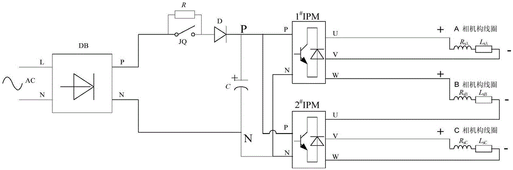
[0034] refer to figure 1 As shown, the three-phase single-coil permanent magnet mechanism drive circuit based on dual IPMs of the present invention includes a capacitor charging circuit and a three-phase single-coil permanent magnet mechanism coil excitation circuit based on dual IPMs;

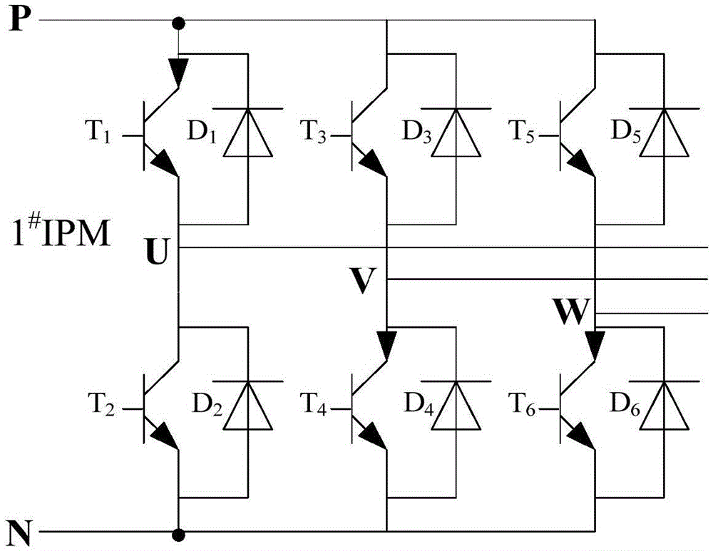
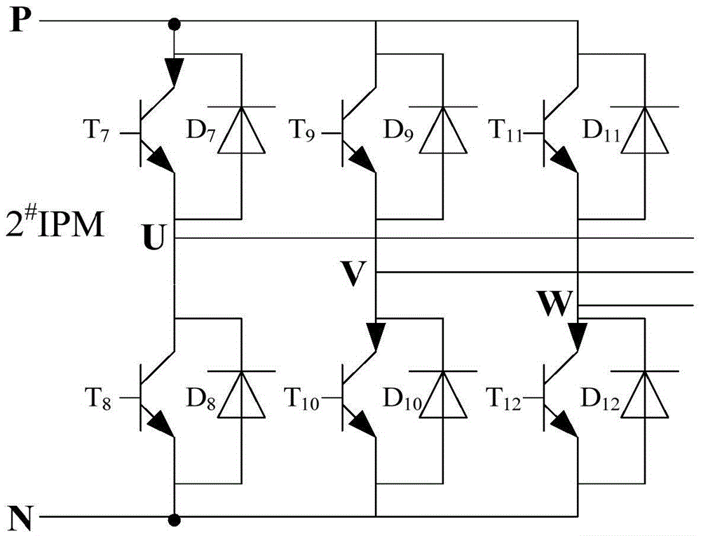
[0035] The capacitor charging circuit is composed of a single-phase alternating current AC, a single-phase uncontrolled rectifier bridge DB, an anti-surge resistor R, a high-power relay JQ, a reverse diode D, and a large-capacity capacitor C; the three-phase single-coil based on dual IPM The permanent magnet mechanism coil excitation circuit includes: 1 # IPM, 2 # IPM and A-phase mechanism coil (by the coil resistance R sA , coil inductance L sA Composition), B-phase mechanism coil (composed of coil resistance R sB , coil inductance L s...


PUM


Abstract

The invention provides a three-phase single-coil permanent magnet mechanism driving circuit based on double IPMs. The three-phase single-coil permanent magnet mechanism driving circuit based on double IPMs comprises a capacitor charging circuit and a three-phase single-coil permanent magnet mechanism coil exciter circuit based on double IPMs; the capacitor charging circuit is composed of single-phase AC power, a single-phase uncontrolled rectifier bridge, an inrush current-preventing resistor, a high-power relay, a backward diode and a large-capacity capacitor; the three-phase single-coil permanent magnet mechanism coil exciter circuit based on double IPMs comprises 1#IPM, 2#IPM, an A-phase mechanism coil, a B-phase mechanism coil and a C-phase mechanism coil. The working method of three-phase single-coil permanent magnet mechanism driving circuit based on double IPMs comprises that the single-phase AC power is rectified to charge the large-capacity capacitor, and the 1#IPM and the 2#IPM are used for controlling the large-capacity capacitor to discharge, and therefore, excitation on the A-phase mechanism coil, the B-phase mechanism coil and the C-phase mechanism coil is completed. The three-phase single-coil permanent magnet mechanism driving circuit based on double IPMs has the advantages that the 1#IPM and the 2#IPM are controlled to be switched on according to a specific time sequence so that intelligent control on the charging and discharging time of each phase of coil can be realized, and meanwhile, the on time sequence of the switching tube of the exciter circuit of each phase of coil is controlled according to the specific time sequence, and therefore, the problem of follow current after the switching tube is switched off in the opening and closing process is effectively solved and the transient overvoltage is avoided.

Description

technical field [0001] The invention relates to the technical field of permanent magnet coil drive, in particular to a dual IPM-based three-phase single-coil permanent magnet mechanism drive circuit and a working method thereof. Background technique [0002] The drive mode of the existing permanent magnet mechanism is realized by using a single-chip microcomputer or DSP to control the switch tube (usually a thyristor) to control the discharge of the capacitor. The capacitor charging and discharging circuit is either based on a diode rectifier circuit or uses a storage battery. During the capacitor discharge process, the discharge current cannot be controlled, and an overvoltage is generated during the switch off process. At present, the driving circuit of the permanent magnet mechanism is usually a three-phase linkage type. It is a technical problem in this field to realize the phase separation operation to solve the charge and discharge time and voltage control of the sing...

Claims


Application Information

Patent Timeline
Patent Type & Authority Patents(China)
IPC IPC(8): H02M3/07H02M1/32
Inventor 刘波陈轩恕江栋兰贞波王卓杨景刚
Owner WUHAN NARI LIABILITY OF STATE GRID ELECTRIC POWER RES INST
Why Eureka
Try Eureka