Eureka AIR delivers breakthrough ideas for toughest innovation challenges, trusted by R&D personnel around the world.

Organic light-emitting device and image display system comprising organic light-emitting device

An organic light-emitting device, organic technology, applied in electrical components, circuits, diodes, etc., can solve problems such as color degradation, uneven pixel size, and complicated steps

Active Publication Date: 2014-12-17
INNOLUX CORP
View PDF4 Cites 11 Cited by
  • Summary
  • Abstract
  • Description
  • Claims
  • Application Information

AI Technical Summary

Problems solved by technology

However, in the full-color organic light-emitting device formed by the three-color light-emitting layer method, the red, blue and green organic light-emitting diode material layers are deposited through separate masks. Such a manufacturing process is not only complicated in steps, but also The alignment requirements for the mask also need to be very precise, and it is easy to cause shadowing effects and uneven pixel sizes
In addition, since the aging rates of red, blue and green organic light emitting diode materials are different, the active full-color organic light emitting device is prone to color deterioration after a period of use. phenomenon occurs

Method used


Image

  • Organic light-emitting device and image display system comprising organic light-emitting device
  • Organic light-emitting device and image display system comprising organic light-emitting device
  • Organic light-emitting device and image display system comprising organic light-emitting device

Examples


Embodiment Construction

[0050] Hereinafter, each embodiment is described in detail and examples accompanied by accompanying drawings are used as a reference basis of the present invention. And in the drawings, the shapes or thicknesses of the embodiments may be enlarged, and marked for simplicity or convenience. Furthermore, parts of the components in the drawings will be described separately. It should be noted that the components not shown or described in the drawings are forms known to those skilled in the art. In addition, specific The examples are only for revealing specific methods used in the present invention, and are not intended to limit the present invention.

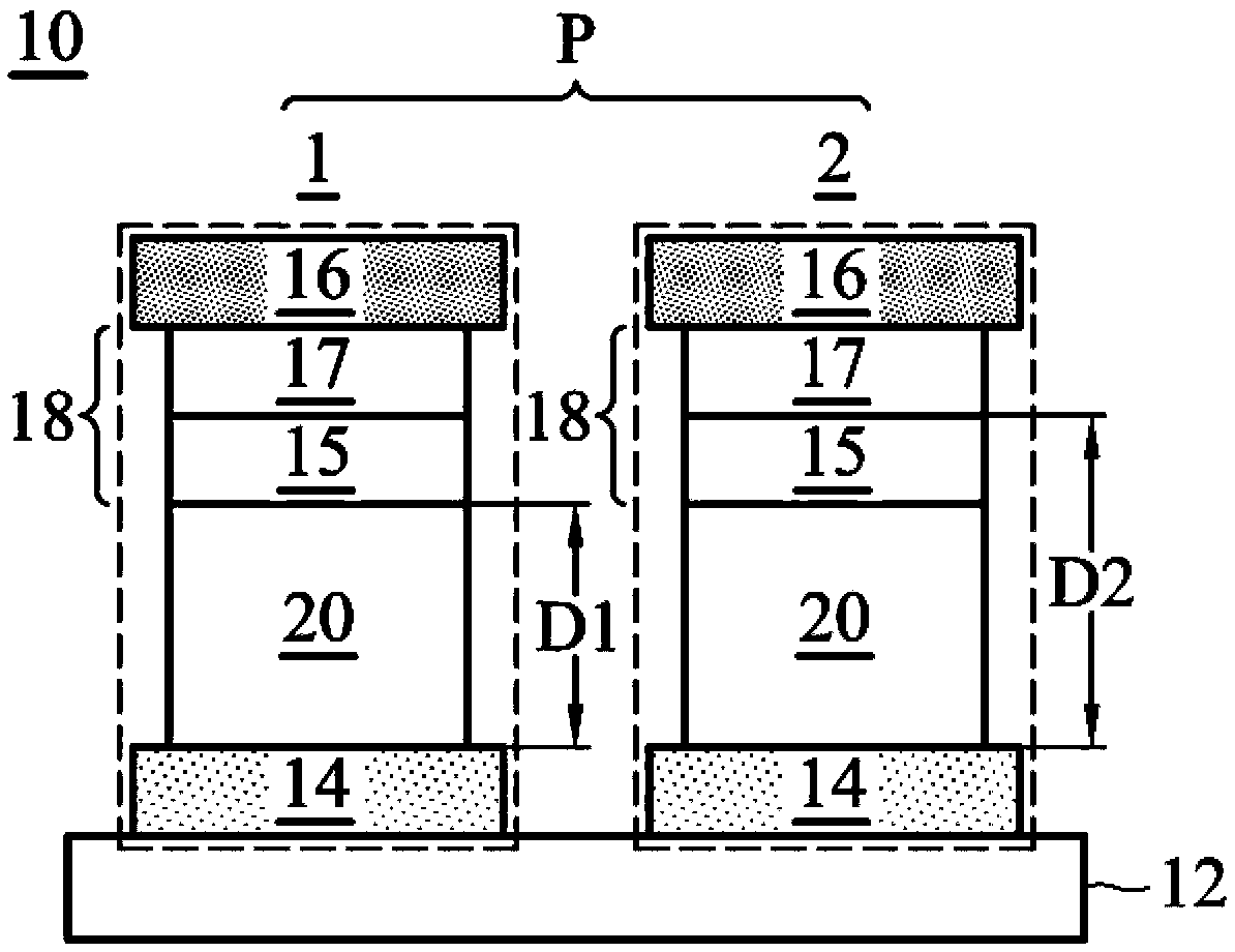
[0051] An embodiment of the present invention discloses an organic light-emitting device 10, please refer to figure 1 , including a substrate 12; and an organic light emitting pixel array (not shown), wherein the organic light emitting pixel array includes a plurality of pixels P, each pixel P includes at least a first pixel 1, and...


PUM

PropertyMeasurementUnit
Lengthaaaaaaaaaa

Abstract

The invention discloses an organic light-emitting device and an image display system comprising the organic light-emitting device. The organic light-emitting device comprises a substrate and an organic light-emitting pixel array arranged on the substrate, wherein the organic light-emitting pixel array comprises a plurality of pixels; each pixel comprises a first sub-pixel and a second sub-pixel; each sub-pixel comprises a first electrode, an organic light-emitting unit and a second electrode; an optical path adjusting layer is arranged between the first electrode and the organic light-emitting unit or between the second electrode and the organic light-emitting unit; and the optical path adjusting layer of each first sub-pixel and the optical path adjusting layer of each second sub-pixel are substantially the same in thickness.

Description

technical field [0001] The present invention relates to an organic light-emitting device, more particularly to an organic light-emitting device with high light extraction efficiency. Background technique [0002] In recent years, with the advancement of electronic product development technology and its increasingly wide application, such as the advent of mobile phones, PDAs and notebook computers, the development of flat-panel displays with smaller volume and power consumption characteristics compared with traditional displays The demand is increasing day by day, becoming one of the most important electronic application products at present. Among the flat panel displays, organic light emitting components will undoubtedly become the best choice for the next generation of flat panel displays due to their characteristics such as self-illumination, high brightness, wide viewing angle, high response speed and easy manufacturing process. [0003] Organic light-emitting devices ar...

Claims


Application Information

Patent Timeline
IPC IPC(8): H01L51/52H01L51/50H01L27/32
CPCH10K59/32H10K50/85H10K50/19
Inventor 周政旭林金住卢英瑞林彦廷许名宏
Owner INNOLUX CORP
Why Eureka
Eureka Blog
Learn More