
PSM high-voltage power supply control system based on MCU and FPGA

A high-voltage power supply and control system technology, applied in the direction of electrical program control, sequence/logic controller program control, etc., can solve the problem that the controller is difficult to take into account at the same time, improve the difficulty of control system design and manufacture, and the time domain span is large, etc. question

Inactive Publication Date: 2014-12-17
INST OF PLASMA PHYSICS CHINESE ACAD OF SCI
View PDF3 Cites 11 Cited by
  • Summary
  • Abstract
  • Description
  • Claims
  • Application Information

AI Technical Summary

Problems solved by technology

[0007] (1) The number of control objects increases. In addition to 10kV AC switches such as circuit breakers and contactors in the PSM high-voltage power supply system, the number of DC side switches has increased from a few (1 to 2) to nearly a hundred (depending on the number of modules). The increase of control objects obviously increases the difficulty of design and manufacture of the control system;
[0008] (2) The control process is more complicated. The PSM high-voltage power supply has to go through several switching processes before and after operation, and all logic control and sequence control need to be automatically realized by the control system;
[0009] (3) The PSM high-voltage power supply has higher requirements on the operating speed and accuracy of the control system. The pulse timing control accuracy varies from microseconds to several seconds, and the time domain span is very large. It is difficult for general controllers to take care of it at the same time;
[0010] (4) In order to meet various complex operating requirements of physical experiments, in the design of the high-voltage power supply control system, a variety of operating modes are added, which further increases the difficulty of the design and manufacture of the control system

Method used


Image

  • PSM high-voltage power supply control system based on MCU and FPGA
  • PSM high-voltage power supply control system based on MCU and FPGA
  • PSM high-voltage power supply control system based on MCU and FPGA

Examples


Embodiment Construction

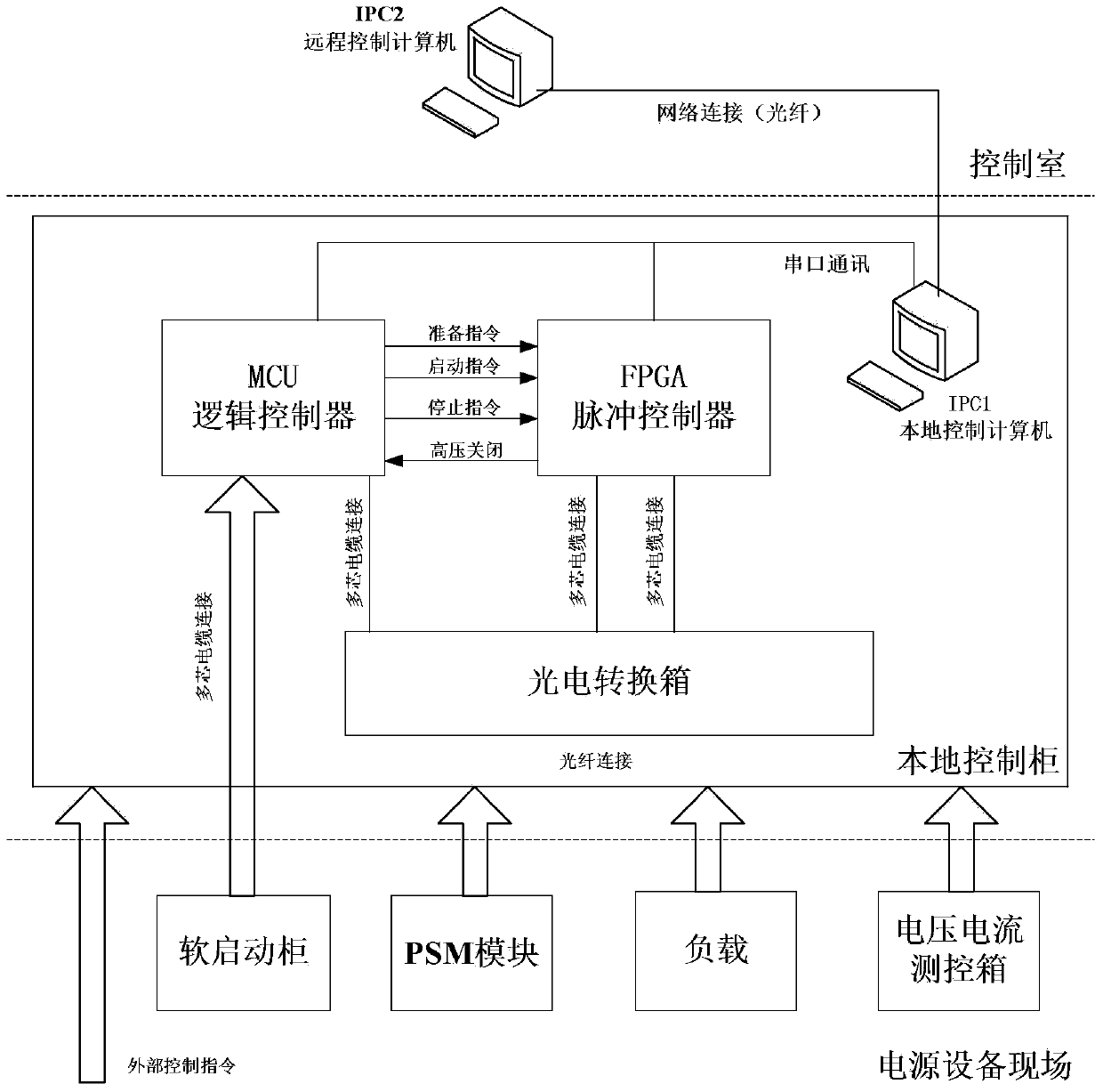
[0034] Such as figure 1 As shown, a PSM high-voltage power supply control system based on MCU and FPGA includes an MCU logic controller and an FPGA pulse controller located in a local control cabinet, and a host computer connected to the MCU logic controller and FPGA pulse controller system and high-voltage power supply field equipment;

[0035]Described upper computer system comprises local control computer IPC1 and remote control computer IPC2 and the control software of matching; Described MCU logic controller and FPGA pulse controller and local control computer IPC1 adopt RS232 serial port communication, local control computer IPC1 and control The remote control computer IPC2 in the room communicates through the network;

[0036] Described high-voltage power field equipment comprises PSM module, voltage and current measurement and control equipment and soft-start contactor cabinet; Described MCU logic controller and FPGA pulse controller are connected to photoelectric con...


PUM


Abstract

The invention discloses a PSM high-voltage power supply control system based on an MCU and an FPGA. The system comprises an MCU logical controller and an FPGA pulse controller. The MCU logical controller and the FPGA pulse controller is communicated with an IPC1 (industrial personal computer) through an RS232 serial port. The IPC1 and an IPC2 form an upper computer system matched with control software. The MCU logical controller and the FPGA pulse controller are connected with high-voltage power supply system parts based on the PSM technology through optical fibers. The MCU logical controller and the FPGA pulse controller execute external signal instructions and control the operation of the parts of the high-voltage power supply system according to the power supply operation mode input by the upper computer control system. The control system has the advantages that the control system is designed by combining the MCU and the FPGA, and technical guarantee is provided for the stable operation of a 140GHz electronic cyclotron resonance heating system on an EAST nuclear fusion device.

Description

technical field [0001] The invention relates to a high-voltage power supply control system, in particular to a high-voltage power supply system control system based on PSM technology. Background technique [0002] As one of the most important and complex systems in the tokamak, the auxiliary heating system has always been the focus of development in various international devices. Corresponding to the development trend of the tokamak from pulse to steady state, the auxiliary heating high-voltage power supply has also experienced a transition from pulse mode to To the development stage of long pulse and even steady state mode, as the latest technology researched at home and abroad in recent years, PSM switching power supply technology has developed rapidly and has been successfully applied in a large number of auxiliary heating high voltage power supply systems. [0003] With the deepening of the tokamak physical experiment, higher and more stringent requirements are put forwa...

Claims


Application Information

Patent Timeline
IPC IPC(8): G05B19/04
Inventor 张健韦维孙浩章郭斐吴友国沈晓岭黄懿赟
Owner INST OF PLASMA PHYSICS CHINESE ACAD OF SCI
Learn More