Uniform powdery material feeding device
A powdery material, uniform technology, applied in the field of powdery material uniform feeding device, can solve the problems of uneven feeding, high speed reducer, high motor speed, improve uniformity, high starting torque, high control accuracy Effect
- Summary
- Abstract
- Description
- Claims
- Application Information
AI Technical Summary
Problems solved by technology
Method used
Image

Examples
Embodiment 1
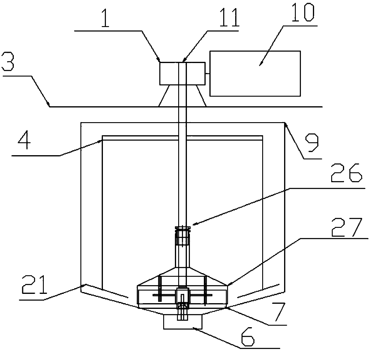
[0026] Embodiment 1: a kind of powdery material uniform feeding device, its structure is as figure 1 , Image 6 , Figure 7 , Figure 8 , Figure 9 with Figure 10 Shown: includes a tank body 9, the top of the tank body 9 is provided with a stepping motor 10 and a reducer 1, the stepping motor 10 is connected to the reducer 1, and the reducer 1 transmits power to the transmission shaft 11, which is located in the tank body 9 The middle and upper part of the transmission shaft 11 is connected with the turning knife fixed frame 4, and the turning knife fixed frame 4 is connected with the turning knife 21 for turning the material in the tank body 9, and the lower end of the transmission shaft 11 is connected with the uniform feeding The control module A27 is connected.
[0027] The top of the tank body 9 is provided with a speed reducer fixed bracket 3, and the speed reducer 1 is connected with the stepping motor 10 and installed and fixed on the top of the speed reducer fix...
Embodiment 2
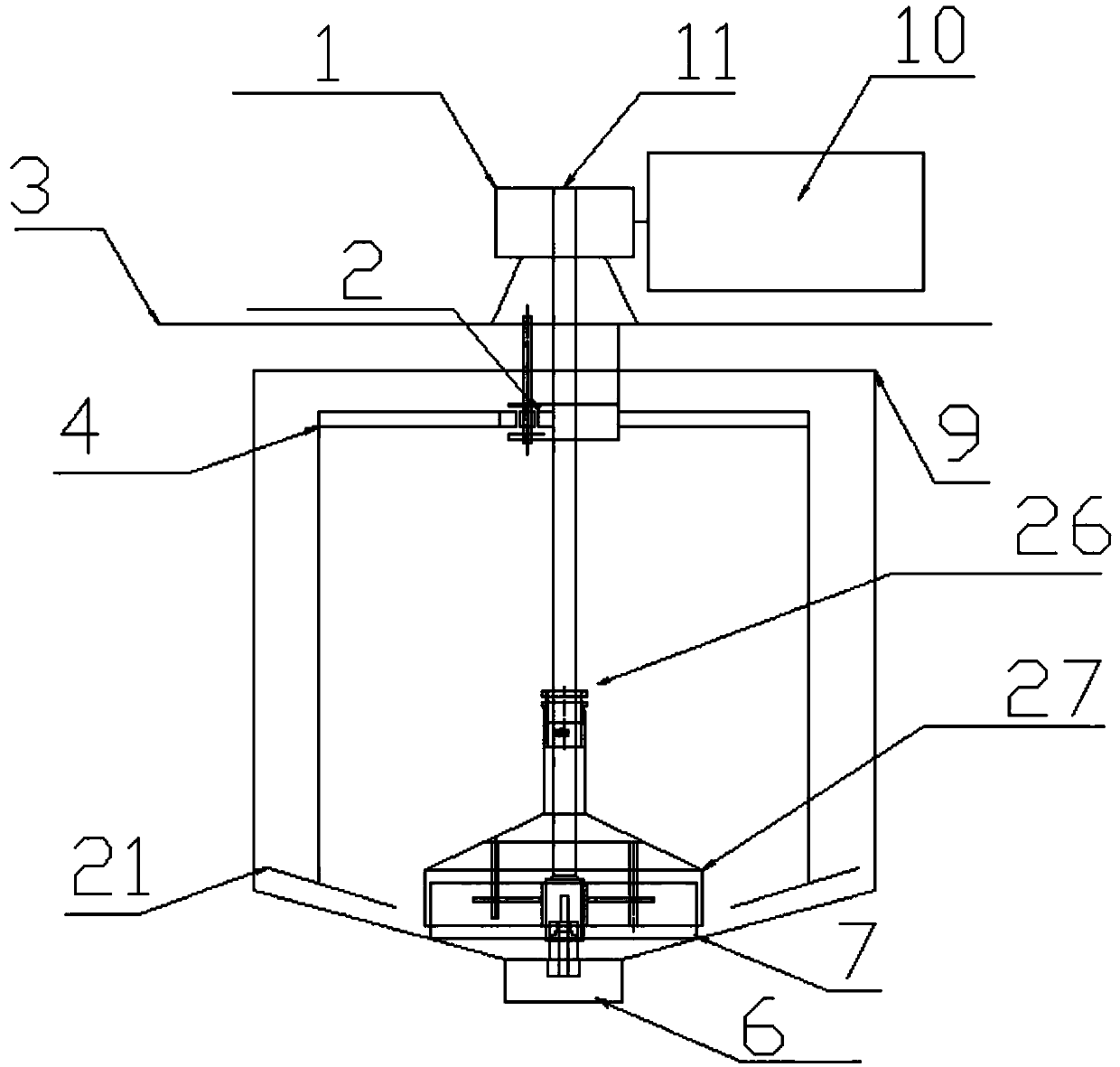
[0047] Embodiment 2: a kind of powdery material uniform feeding device, its structure is as figure 2 , Figure 5 , Image 6 , Figure 7 , Figure 8 , Figure 9 with Figure 10 Shown: includes a tank body 9, the top of the tank body 9 is provided with a stepping motor 10 and a reducer 1, the stepping motor 10 is connected to the reducer 1, and the reducer 1 transmits power to the transmission shaft 11, which is located in the tank body 9 The middle and upper part of the transmission shaft 11 is connected with the turning knife fixed frame 4, and the turning knife fixed frame 4 is connected with the turning knife 21 for turning the material in the tank body 9, and the lower end of the transmission shaft 11 is connected with the uniform feeding The control module A27 is connected.
[0048] The top of the tank body 9 is provided with a reducer fixing bracket 3 , and the reducer 1 is connected with the stepping motor 10 and installed and fixed on the reducer fixing bracket 3...
Embodiment 3
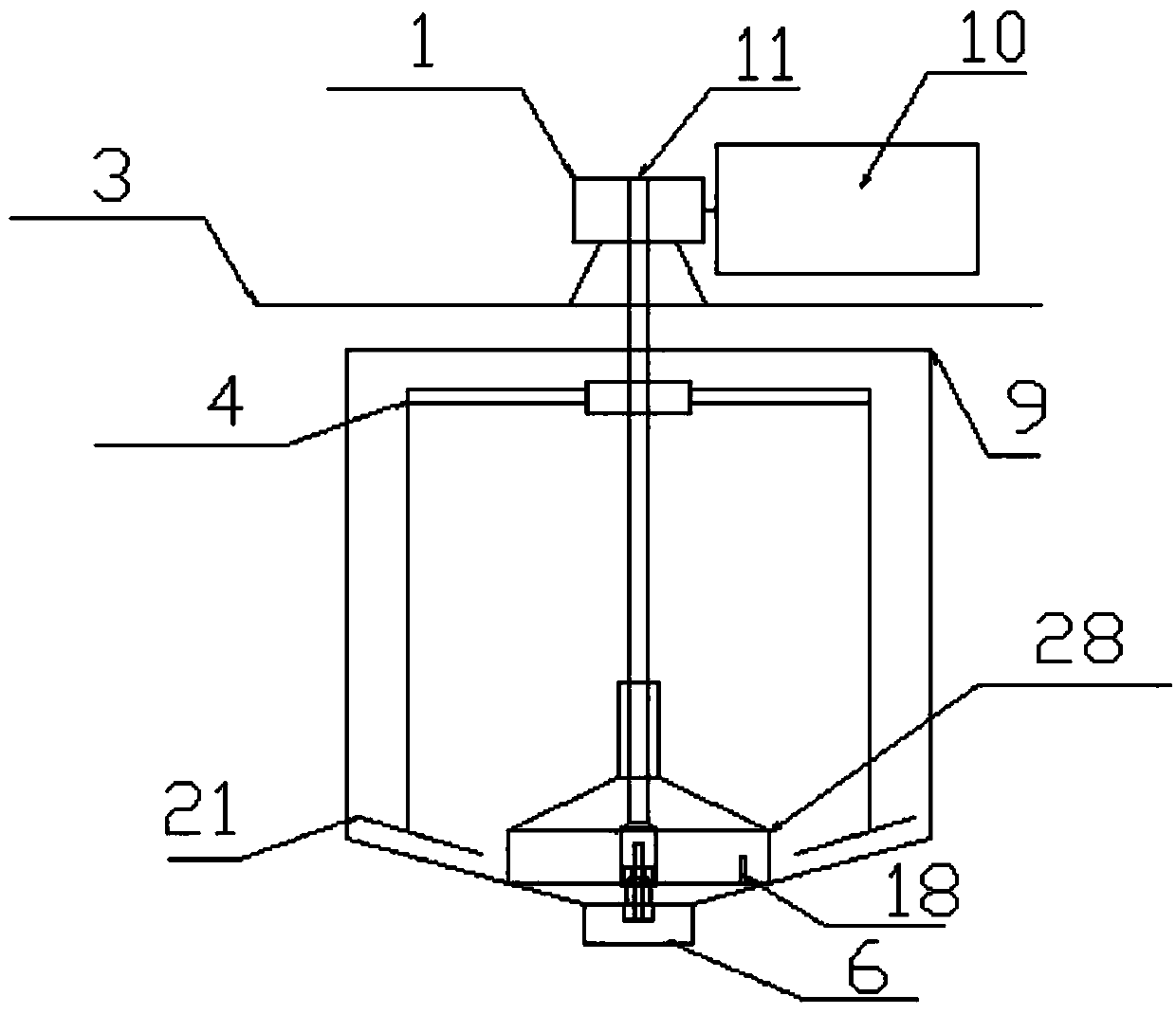
[0071] Embodiment 3: a kind of powdery material uniform feeding device, its structure is as image 3 with Figure 11 Shown: includes a tank body 9, the top of the tank body 9 is provided with a stepping motor 10 and a reducer 1, the stepping motor 10 is connected to the reducer 1, and the reducer 1 transmits power to the transmission shaft 11, which is located in the tank body 9 The middle and upper part of the transmission shaft 11 is connected with the turning knife fixed frame 4, and the turning knife fixed frame 4 is connected with the turning knife 21 for turning the material in the tank body 9, and the lower end of the transmission shaft 11 is connected with the uniform feeding The control module B28 is connected.
[0072] The top of the tank body 9 is provided with a speed reducer fixed bracket 3, and the speed reducer 1 is connected with the stepping motor 10 and installed and fixed on the top of the speed reducer fixed bracket 3.
[0073] The uniform feeding control...
PUM
 Abstract
Description
Claims
Application Information
 - Generate Ideas
- Intellectual Property
- Life Sciences
- Materials
- Tech Scout
- Unparalleled Data Quality
- Higher Quality Content
- 60% Fewer Hallucinations
Browse by: Latest US Patents, China's latest patents, Technical Efficacy Thesaurus, Application Domain, Technology Topic, Popular Technical Reports.
© 2025 PatSnap. All rights reserved.Legal|Privacy policy|Modern Slavery Act Transparency Statement|Sitemap|About US| Contact US: help@patsnap.com