
Special precoated sand for cast of high alloy material

A technology of coated sand and alloy, which is applied in the direction of casting moulds, casting molding equipment, metal processing equipment, etc., can solve the problems that cannot meet the requirements of high-alloy castings, and achieve the effects of small expansion rate, fine structure and high application value

Inactive Publication Date: 2014-12-17
西峡飞龙特种铸造有限公司
View PDF6 Cites 18 Cited by
  • Summary
  • Abstract
  • Description
  • Claims
  • Application Information

AI Technical Summary

Problems solved by technology

[0005] However, the coated sand produced for various casting defects has higher and higher requirements according to the casting material, and more and more new casting material standards have been developed. A series of high-alloy casting materials are becoming more and more common, while the original Some special coated sands produced solely for various casting defects are increasingly unable to meet the requirements of high-alloy castings

Method used


Image

  • Special precoated sand for cast of high alloy material
  • Special precoated sand for cast of high alloy material
  • Special precoated sand for cast of high alloy material

Examples


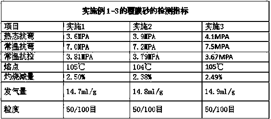
Embodiment 1

[0029] The composition ratio of the special coated sand of the high alloy material casting of the present invention is as follows:

[0030] Special coated sand, including raw sand, lubricants, binders, curing agents and coupling agents, of which recycled sand accounts for 50% of the total mass of original sand; Baozhu sand accounts for 35% of the total mass of original sand; magnetite sand accounts for 15% of the total mass of the sand, the binder accounts for 1.8% of the total mass of the original sand; the curing agent is 10% of the binder mass; the lubricant is 6% of the binder mass; the coupling agent is 6% of the binder mass 1.5%.

Embodiment 2

[0032] The composition ratio of the special coated sand of the high alloy material casting of the present invention is as follows:

[0033] Special coated sand, including raw sand, lubricants, binders, curing agents and coupling agents, of which recycled sand accounts for 50% of the total mass of original sand; Baozhu sand accounts for 35% of the total mass of original sand; magnetite sand accounts for 15% of the total mass of the sand, the binder accounts for 1.9% of the total mass of the original sand; the curing agent is 9% of the binder mass; the lubricant is 8% of the binder mass; the coupling agent is 8% of the binder mass 2%.

Embodiment 3

[0035] The composition ratio of the special coated sand of the high alloy material casting of the present invention is as follows:

[0036] Special coated sand, including raw sand, lubricants, binders, curing agents and coupling agents, of which recycled sand accounts for 50% of the total mass of original sand; Baozhu sand accounts for 35% of the total mass of original sand; magnetite sand accounts for 15% of the total mass of the sand, the binder accounts for 1.7% of the total mass of the original sand; the curing agent is 11% of the binder mass; the lubricant is 7% of the binder mass; the coupling agent is 7% of the binder mass 1%.


PUM

PropertyMeasurementUnit
Gas outputaaaaaaaaaa

Abstract

The invention discloses special precoated sand for cast of high alloy material. The sand comprises roughing sand, a lubricant, an adhesive, a curing agent and a coupling agent. The adhesive is 1.7-1.9 % of the total weight of the roughing sand. The curing agent is 9-11 % of the weight of the adhesive. The lubricant is 6-8 % of the weight of the adhesive. The coupling agent is 1-2 % of the weight of the adhesive. The roughing sand comprises reclaimed sand, cerabeads, and magnetic sand. The reclaimed sand is 50-65 % of the total weight of the roughing sand. The cerabeads are 25-35 % of the total weight of the roughing sand. The magnetic sand is 10-15 % of the total weight of the roughing sand. The sand has various superior properties of high temperature resistance, high strength, low expansion, low gas release and easy collapse. The sand can guarantee that the process of cast of high alloy material can be smoothly performed, and the production efficiency is improved.

Description

technical field [0001] The invention belongs to the technical field of coated sand production, in particular to a special coated sand for high-alloy castings. Background technique [0002] Coated sand is often used in steel castings and iron castings. The surface of the sand grains is covered with a layer of solid resin film molding sand or core sand before molding. There are two coating processes: cold method and hot method: the resin is dissolved in ethanol in the cold method , and add urotropine during the sand mixing process, so that the two are coated on the surface of the sand grains, and the ethanol volatilizes to obtain coated sand; the thermal method preheats the sand to a certain temperature, adds resin to make it melt, and stirs to make the resin coated Cover the surface of sand grains, add urotropine aqueous solution and lubricant, cool, crush, and sieve to obtain coated sand. [0003] At present, domestic coated sand factories are able to produce coated...

Claims


Application Information

Patent Timeline
IPC IPC(8): B22C1/02B22C1/00B22C1/22
Inventor 刘松奇王瑞金闫国富彭德楼齐晓军
Owner 西峡飞龙特种铸造有限公司
Learn More