Hollow rotary transformer

A rotary transformer, hollow technology, applied in the direction of transformers, inductors, electrical components, etc., can solve the problems of low energy transfer efficiency and information transfer needs, and achieve the effect of meeting the requirements of the electromagnetic environment, light weight, and stable transmission

Inactive Publication Date: 2014-12-10
XIAN AVIATION BRAKE TECH
View PDF4 Cites 6 Cited by
  • Summary
  • Abstract
  • Description
  • Claims
  • Application Information

AI Technical Summary

Problems solved by technology

[0006] In order to overcome the low energy transfer efficiency existing in the prior art and the inability to meet the needs of energy and information transfer in the rotating state under airborne conditions, the present invention proposes a hollow rotary transformer

Method used


Image

  • Hollow rotary transformer
  • Hollow rotary transformer
  • Hollow rotary transformer

Examples


Embodiment Construction

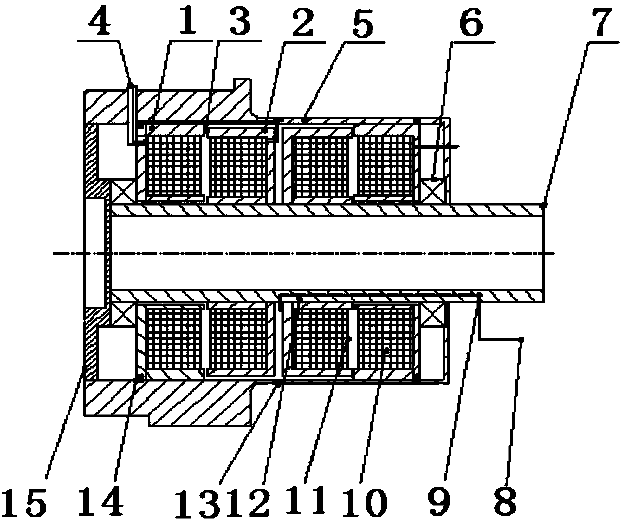
[0041] This embodiment is a hollow rotary transformer, comprising two closed magnetic circuits, a housing 5, a pair of bearings 6, a hollow shaft 7, a stator resistance 10 and a rotor resistance 11, and the closed magnetic circuit is composed of a stator 1 and a rotor resistance 11. A closed magnetic flux channel composed of a rotor 2, and in each closed magnetic circuit, the magnetic gap 3 at the joint between the stator and the rotor is 0.5 mm. Both the stator 1 and the rotor 2 are made of permalloy.

[0042] In this embodiment: a pair of bearings 6 are sleeved on the hollow shaft 7 . The two closed magnetic circuits are sleeved on the hollow shaft 7 and located between the pair of bearings; the stators in the two closed magnetic circuits are in clearance fit with the hollow shaft, and the two closed magnetic circuits The rotor in the magnetic circuit rotates synchronously with this hollow shaft. After the two closed magnetic circuits are fitted on the hollow shaft, the st...


PUM


Abstract

The invention discloses a hollow rotary transformer. Stators in two closed magnetic circuits are in clearance fit with a hollow shaft, rotors in the two closed magnetic circuits rotate synchronously with the hollow shaft, and the stators and the rotors in the two closed magnetic circuits are arranged on the hollow shaft in the mode of stator-rotor-rotor-stator. Stator outgoing lines of the stators are connected with an electric connector outside a shell, and rotor outgoing lines of the rotors are connected with an electric connector arranged on the hollow shaft in a sleeved mode. According to the hollow rotary transformer, the stators and the rotors are of a non-contact structure, induction couplers of a traditional transformer are separated, a primary winding and a secondary winding are wound around different magnetic core structures respectively, and therefore non-contact energy coupling between a power supply and a load is achieved. After being electrified, the stators and the rotors generate induced electromotive force through magnetizers and carry out energy coupling through magnetic gaps. Due to the fact that the electromagnetic coupling step is completely enclosed in a rotary cavity, leakage of electromagnetic waves is avoided, and the requirements of electromagnetic environments and electromagnetic compatibility tests in the onboard state can be met.

Description

technical field [0001] The invention relates to the field of aircraft braking devices, in particular to a hollow rotary transformer. Background technique [0002] In foreign modern and advanced aircraft, the aircraft tire pressure monitoring system TPMS (Tire Pressure Monitoring System) has been widely used, such as: AIRBUS, BOEING and DASSAULT in many models, including the latest A380 aircraft is also equipped with tire pressure monitoring system Monitoring System. It is a technology that keeps aircraft safe. The tire pressure monitoring system monitors the internal air pressure of the tire, provides the actual tire pressure to the crew or maintenance personnel through the data bus and the display, and can give an alarm for the low pressure and blowout of the tire. At the same time, when the temperature of the brake device exceeds 400°C, Turn on the fan to cool down. In daily maintenance, this technology reduces the temperature of the brake device in time to ensure the s...

Claims


Application Information

Patent Timeline
IPC IPC(8): H01F38/18H02K1/06
Inventor 张驰马晓军王学锋农贵军牛祖军曹永
Owner XIAN AVIATION BRAKE TECH
Why Eureka
Try Eureka