
An auxiliary coupling method and auxiliary device for coupling an optical waveguide chip and a PD array

A waveguide chip and auxiliary device technology, applied in the field of optical communication, to achieve the effects of short length, convenient coupling and small volume

Active Publication Date: 2017-02-22
GUANGXUN SCI & TECH WUHAN
View PDF6 Cites 0 Cited by
  • Summary
  • Abstract
  • Description
  • Claims
  • Application Information

AI Technical Summary

Problems solved by technology

[0005] In order to solve the problem that active coupling and alignment cannot be performed without input light in the prior art, the present invention provides a compact coupling auxiliary input light source method and its auxiliary device. With the auxiliary input light source, the waveguide chip and PD array can be monitored. The magnitude of the coupling current enables active alignment. The auxiliary light source can be removed after the coupling is completed, which facilitates the alignment of the optical path in the next step.

Method used


Image

  • An auxiliary coupling method and auxiliary device for coupling an optical waveguide chip and a PD array
  • An auxiliary coupling method and auxiliary device for coupling an optical waveguide chip and a PD array
  • An auxiliary coupling method and auxiliary device for coupling an optical waveguide chip and a PD array

Examples


Embodiment Construction

[0033] Further description will be given below in conjunction with the accompanying drawings and embodiments.

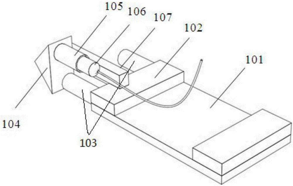
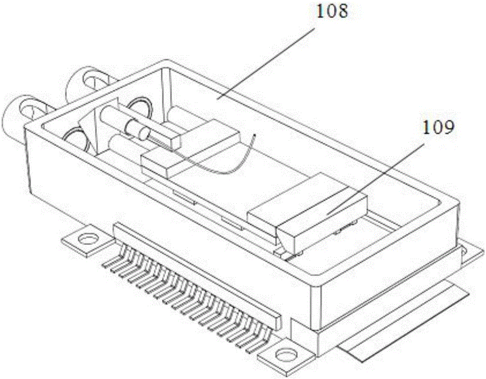
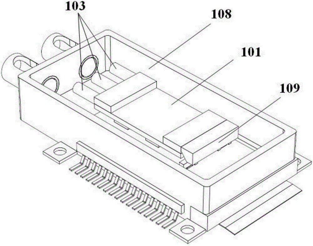
[0034] The present invention proposes a method for providing an auxiliary input light source for the waveguide chip 101. The coupling structure between the waveguide chip 101 and the PD array 111 adopts the patented "optical waveguide chip and PD array lens coupling device application number: 201310433022" structure. In the above patent, the heat sink 114 is located in the miniaturized tube shell 108, the PD array 111 is pasted on the heat sink 114 by conductive adhesive, and the heat sink 114 is provided with a lens spacer 112, which is two brackets Combination, the two brackets are arranged on both sides of the PD array 111; the lens pad 112 is provided with a strip-shaped lens array 110; an output reflective prism 109 is bonded on the cover glass 102 at the output end of the waveguide chip 101, and the prism The function is to make the output light path turn 90 de...


PUM


Abstract

The invention discloses an assisting method and device for coupling of an optical waveguide chip and a PD (photo diode) array. The assisting method includes manufacturing a collimation device and the assisting device adhered with a right-angle reflecting prism, detachably fixing the right-angle reflecting prism and the waveguide chip so that an external light source perpendicularly irradiates the right-angle reflecting prism through the collimation device and light perpendicularly emits to be coupled with an input end of the waveguide chip to the waveguide chip after being reflected twice by the right-angle reflecting prism, and demounting the assisting device on the waveguide chip after the waveguide chip is coupled with the PD array. By the assisting method, the inputted light source irradiates the waveguide chip after refracted by 180 degrees via the right-angle reflecting prism, and inputted light path is folded through the right-angle reflecting prism; the integral light path is small in size and shorter, and active coupling packaging can be realized in a shorter pipe shell.

Description

technical field [0001] The invention belongs to the field of optical communication, relates to a photoelectric module in the optical communication technology, in particular to the optical transmission medium (optical fiber, optical waveguide) in the optical module and the optical semiconductor element such as: semiconductor laser, PD array (Photo-Diode, photodiode) Between The photoelectric coupling auxiliary input optical path coupling method and its input auxiliary device. Background technique [0002] With the emergence of smart devices, cloud computing, and the Internet of Things, the demand for network bandwidth continues to rise, and it is imminent to increase the system transmission rate, and 100G and higher rate transmission systems have been applied. In these systems, the optical transmitter and optical receiver are the key components. They involve photoelectric conversion, and photoelectric conversion involves the design of photoelectric conversion structure. The s...

Claims


Application Information

Patent Timeline
Patent Type & Authority Patents(China)
IPC IPC(8): G02B6/34G02B6/32
Inventor 石川习华丽江雄梁雪瑞
Owner GUANGXUN SCI & TECH WUHAN
Learn More