
Method for Optimizing Differential Cylindrical Image Motion LiDAR

A lidar and beam technology, applied in the field of optimizing differential beam image motion lidar, can solve problems such as the inability to detect the average tilt of the wavefront, and achieve the effect of improving data quality

Active Publication Date: 2016-11-30
HEFEI INSTITUTES OF PHYSICAL SCIENCE - CHINESE ACAD OF SCI
View PDF2 Cites 0 Cited by
  • Summary
  • Abstract
  • Description
  • Claims
  • Application Information

AI Technical Summary

Problems solved by technology

However, the differential column image motion radar can only measure the distance change of the laser beam imaging on the focal plane; because the existing differential column image motion radar uses two sub-aperture designs, it can only obtain the average wavefront tilt in the direction of the sub-aperture connection line according to the imaging spacing , but it is impossible to detect the average tilt of the wavefront perpendicular to the line connecting the sub-apertures
Due to the randomness of turbulence, there is an improvement in the method of obtaining the atmospheric coherence length by only using the wavefront average tilt in one-dimensional direction; the differential cylindrical image of the atmospheric coherence length profile can be obtained by using the wavefront average tilt in two orthogonal directions at the same time Motion Radar has not been reported yet

Method used


Image

  • Method for Optimizing Differential Cylindrical Image Motion LiDAR
  • Method for Optimizing Differential Cylindrical Image Motion LiDAR
  • Method for Optimizing Differential Cylindrical Image Motion LiDAR

Examples


Embodiment Construction

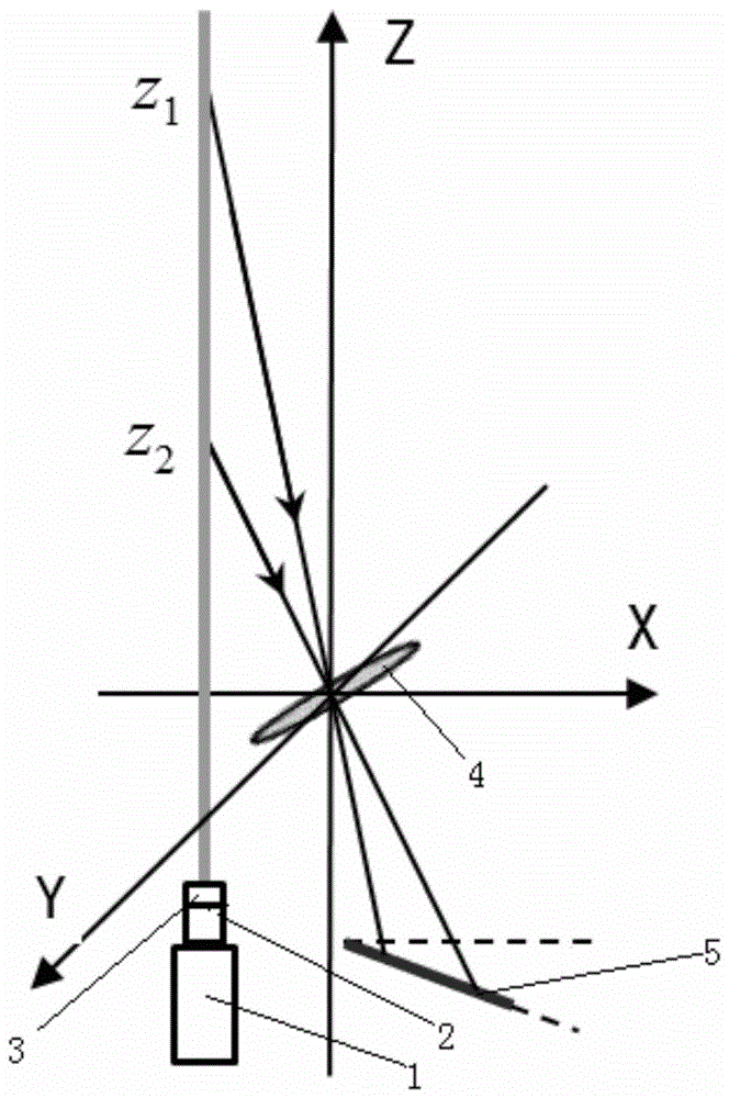
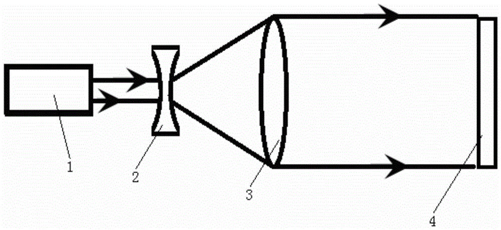
[0011] A method for optimizing differential beam image movement lidar, including a laser 1, a beam expander 2, a convex lens 3 and a receiving telescope 4, the laser light emitted by the laser 1 passes through the beam expander 2 and the convex lens 3 in sequence, and then is received by the receiving telescope 4 Receiving, the front side of the main mirror of the receiving telescope 4 is provided with a block 6, and four sub-apertures 7 are arranged on the block 6, the centers of the four sub-apertures 7 are four points of a square, and a pair of squares The diagonal line is parallel to the vertical plane of the system where the laser 1 emits and receives the telescope 4, and the other diagonal line is perpendicular to the vertical plane of the system. Two kinds of wedge angles are installed on the front side of the four sub-holes 7 diameters. The wedge angle directions of the four wedge mirrors are all perpendicular to the vertical plane of the system, and the angle between t...


PUM


Abstract

The invention discloses a method for optimizing differential light column image motion laser radar. The invention can simultaneously take into account the lateral size of laser beam imaging at different heights on the focal plane through small-caliber collimation and emission of laser beams, and reduces the imaging size of laser beams at different heights. The impact of changes on the measurement accuracy of the atmospheric coherence length; by installing two groups of wedge mirrors whose wedge angle direction is perpendicular to the system plane in front of the four sub-apertures arranged in a square, the differential column image motion radar can use the sub-apertures respectively according to the DIM principle The average wavefront tilt information in the parallel and vertical directions of the connecting line is used to measure the atmospheric coherence length, which solves the problem that the existing differential beam motion radar only uses the wavefront average tilting information in the connecting line direction to measure the atmospheric coherence length; The spacing is greater than the coherence scale of turbulent flow under general turbulent conditions, and the four apertures can obtain two sets of statistically independent atmospheric coherence length profiles at the same time, and averaging the two sets of profiles can improve the data quality of the profiles.

Description

technical field [0001] The invention relates to the field of mechanical and optical design, in particular to a method for optimizing differential beam image motion laser radar. Background technique [0002] The size of the atmospheric coherence length describes the strength of the integral effect of turbulence intensity on the propagation path, and has been widely used in the fields of astronomical site selection and laser communication. The differential image motion (DIM) principle utilizes the average inclination of the wave surface of two sub-aperture detection light waves after passing through the atmosphere, and performs orthogonal decomposition on the average inclination of the wave surface in two directions parallel and perpendicular to the line connecting the centers of the sub-apertures. The relative position change of the target image can be used to obtain the average tilt of the wave surface and then the atmospheric coherence length. The DIM principle overcomes t...

Claims


Application Information

Patent Timeline
Patent Type & Authority Patents(China)
IPC IPC(8): G01S17/89
Inventor 靖旭王英俭侯再红张巳龙于龙昆张守川何枫吴毅
Owner HEFEI INSTITUTES OF PHYSICAL SCIENCE - CHINESE ACAD OF SCI
Learn More