Aero Engine Speed ​​Test System

A technology of aero-engine and test system, applied in the direction of linear/angular velocity measurement, velocity/acceleration/shock measurement, measuring device, etc., can solve the problem of non-compliance with safety and reliability requirements, poor rotational speed measurement accuracy, and intelligent degree low level problem

Active Publication Date: 2015-10-21
QINGDAO CAMPUS AVIATION ENG COLLEGE OF THE PEOPLES LIBERATION ARMY NAVY
View PDF8 Cites 0 Cited by
  • Summary
  • Abstract
  • Description
  • Claims
  • Application Information

AI Technical Summary

Problems solved by technology

When the rotor rotates, the high-speed gearbox drives the drive shaft of the sensor to rotate with a certain speed ratio, so that the tooth plate of the sensor rotates accordingly, and the teeth and tooth gaps in the plate pass through the air gap, that is, the magnetic field of the permanent magnet, and constantly change the magnetic circuit The magnetic resistance of the iron core changes the magnetic flux of the iron core, and finally generates an electrical signal of a certain amplitude and frequency in the sensor coil, and the effective value and frequency of the electrical signal are linearly related to the rotation rate, but in actual operation It is found that since the output signal of the aeroengine is not a standard signal, the above-mentioned speed sensor measurement method cannot obtain accurate speed measurement results, especially during the process of the aircraft from take-off to landing, as the aircraft engine speed frequency decreases from low to high. The current speed sensor measurement method cannot accurately collect the engine speed with a specific acquisition method for the change of the engine rotation frequency, resulting in poor speed measurement accuracy and low intelligence, which does not meet the requirements of the domestic aviation technology field. Aircraft Operation Safety and Reliability Requirements

Method used


Image

  • Aero Engine Speed ​​Test System
  • Aero Engine Speed ​​Test System

Examples


Embodiment 1

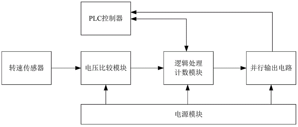
[0018] join figure 1 , an aero-engine speed testing system, comprising: a speed sensor, a voltage comparison module, a logic processing counting module, a PLC controller, a parallel output module and a power supply module;

[0019] The input end of the speed sensor is connected with the high and low pressure rotor through the high-speed gearbox of the aero-engine, and is used to detect the speed signal output by the aero-engine, and the output end of the speed signal of the speed sensor is electrically connected with the voltage comparison module; The sensor includes two speed measurement systems. One is to measure the high-pressure speed sensor at the high-pressure rotor end of the engine. The high-pressure speed sensor is connected to the high-pressure rotor through the high-speed gearbox of the aero-engine to measure the speed of the high-pressure rotor end of the aero-engine. The other is to measure the low-pressure speed of the engine. The low-pressure speed sensor at the...


PUM


Abstract

The invention relates to an aero-engine rotation speed testing system which comprises a rotation speed sensor, a voltage comparison module, a logical processing counting module, a PLC (programmable logic controller), a parallel output module, a power module and two paths of rotation speed measuring systems. One path of the rotation speed measuring system is a high-voltage rotation speed sensor for measuring the high-voltage rotor end of an engine, the other path of the rotation speed measuring system is a low-voltage rotation speed sensor for measuring the low-voltage rotor end of the engine, and rotation speed measuring of high-voltage and low-voltage rotors is achieved. The logical processing counting module is a CPLD chip which converts rotation speed waveforms into digital rotation speed values and outputs the digital rotation speed values through the parallel output module. The parallel output module adopts NPN type triode collectors for open circuit output and can be flexibly connected with various loads. The PLC controls the logical processing counting module to achieve switching between high-speed counting and low-speed counting. By the aero-engine rotation speed testing system, testing accuracy and effectiveness are increased, testing cycle is shortened, energy is saved, labor intensity of workers is lowered, and detecting efficiency of engine performance parameters is increased.

Description

technical field [0001] The invention relates to a measuring device for measuring an aero-engine, in particular to an aero-engine rotational speed testing system. Background technique [0002] The engine is the core equipment of the aircraft and the heart of the aircraft. The performance of the aero-engine directly affects the combat performance and flight safety of the aircraft. At present, the speed measurement of aero-engines is carried out by variable reluctance speed sensors. The basic principle is: in a magnetic circuit composed of permanent magnets, such as an air gap, if the size of the reluctance is changed, the magnetic flux will change. The induction coil passing through the magnetic circuit will induce an alternating electric potential of a certain magnitude, and the frequency of the alternating electric potential is equal to the frequency of the magnetic flux change. When the rotor rotates, the high-speed gearbox drives the drive shaft of the sensor to rotate w...

Claims


Application Information

Patent Timeline
Patent Type & Authority Patents(China)
IPC IPC(8): G01P3/481G01P3/489
Inventor 刘振岗邹刚王哲张玎郭刚王占勇唐有才王海东唐元恒
Owner QINGDAO CAMPUS AVIATION ENG COLLEGE OF THE PEOPLES LIBERATION ARMY NAVY
Why Eureka
Try Eureka