
A solar window ventilation device

A ventilation device and solar energy technology, applied in ventilation systems, space heating and ventilation, heating methods, etc., can solve problems such as poor sealing and isolation effects, air pollution, etc., and prevent polluted dust from entering the room. simple effect

Active Publication Date: 2016-08-10
梁晓军
View PDF6 Cites 0 Cited by
  • Summary
  • Abstract
  • Description
  • Claims
  • Application Information

AI Technical Summary

Problems solved by technology

[0002] At present, the indoor ventilation of residents is mainly carried out in the form of opening windows. In the current situation of serious air pollution, the outdoor air environment has a considerable impact on people's health, and a certain amount of indoor air will also be generated in closed air-conditioned rooms. Therefore, it is very necessary to discharge the indoor polluted air and ensure the circulation and clean exchange of indoor and outdoor air. The patent of "a solar window ventilation device for household use" described in patent number 201320179408. Solar ventilation device, the ventilation device is equipped with louvers, filter screens, fans and solar panels inside and outside the two connected casings. The ventilation duct of the above structure is a horizontal straight-through type. The rainwater is easy to enter the room, and the length of the ventilation pipe is long. The solar panel is located at the tail, which causes the center of gravity of the whole device to be behind, which will have an adverse effect on the glass windows. Therefore, it is necessary to redesign the waterproof and overall structure. At the same time, it is necessary to take into account the structure of the existing glass windows, and the technical solution requires reliability, practicality and implementability

Method used


Image

  • A solar window ventilation device
  • A solar window ventilation device
  • A solar window ventilation device

Examples


Embodiment Construction

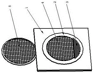
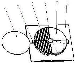
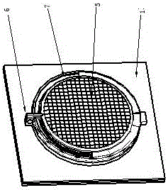
[0028] The embodiment is provided with indoor and outdoor solar panels, two left and right centrifugal fans, the indoor and outdoor solar panels are respectively connected to drive a centrifugal fan, and the control switch is provided with two pairs of contacts to control the two centrifugal fans at the same time, and the bushing is set as T-shaped. The casing, the diameter of the indoor and outdoor solar panels is smaller than the opening diameter of the T-shaped casing, and the external power supply is automatically switched to supply power to the centrifugal fan through a timer at night.

[0029] Such as figure 1 The schematic diagram of the working state of the shown embodiment, the outdoor solar cell panel 4 and the louver 3 are arranged on the outdoor end face of the T-shaped casing 2, and the T-shaped casing 2 is arranged on the glass window 1. During the working state, the indoor solar cell panel 5 And 4 outdoor solar panels facing the sun.

[0030] Such as figure 2...


PUM


Abstract

The invention provides a solar energy window-type ventilation device which comprises a sleeve arranged on a glass window. The surface of the sleeve is provided with outer threads. The sleeve is fixed to the glass window through a locking screw cap. The outdoor end face of the sleeve is provided with a solar cell plate and a shutter, and the indoor end face of the sleeve is provided with a waterproof baffle. A half-cylinder-shaped air bellow is arranged above the position, in the sleeve, of the waterproof baffle, a centrifugal fan is arranged in the half-cylinder-shaped air bellow. Exhaust is sent outside the glass window through the shutter. A centre positioning cylinder is connected with the waterproof baffle and the solar cell panel. A semicircular filter screen grid and a semicircular wind screen form a circular rotating body, and the circular rotating body is fixed to the center positioning cylinder through a manual bolt. According to the solar energy window-type ventilation device, electric power is generated through the solar cell plate at daytime to be supplied to the centrifugal fan so as to conduct indoor ventilation, a timer is automatically connected to an external power source at night to supply power to the centrifugal fan, indoor air ventilation can be effectively kept, air quality in an air-conditioned room is improved, and the solar energy window-type ventilation device has the advantages of saving energy and protecting the environment and being easy to install.

Description

technical field [0001] The invention relates to a ventilation device, in particular to a solar window ventilation device. Background technique [0002] At present, the indoor ventilation of residents is mainly carried out in the form of opening windows. In the current situation of serious air pollution, the outdoor air environment has a considerable impact on people's health, and a certain amount of indoor air will also be generated in closed air-conditioned rooms. Therefore, it is very necessary to discharge the indoor polluted air and ensure the circulation and clean exchange of indoor and outdoor air. The patent of "a household solar window ventilation device" described in Patent No. 201320179408. Solar ventilation device, the ventilation device is equipped with louvers, filter screens, fans and solar panels inside and outside the two connected casings. The ventilation duct of the above structure is a horizontal straight-through type, and the sealing and isolation effect ...

Claims


Application Information

Patent Timeline
Patent Type & Authority Patents(China)
IPC IPC(8): F24F7/007H02S10/00
CPCY02E10/50
Inventor 梁晓军
Owner 梁晓军
Learn More