A hybrid power system of electromagnetic tooth clutch and dual motors
A clutch and cogging technology, applied in the direction of power devices, electric components, pneumatic power devices, etc., can solve the problems of limited torque capacity, large space occupation, heavy weight, etc., and achieve large transmission torque, rapid action, and compact structure Effect
- Summary
- Abstract
- Description
- Claims
- Application Information
AI Technical Summary
Problems solved by technology
Method used
Image
Examples
Embodiment 1
[0045] Embodiment 1 Electromagnetic tooth clutch
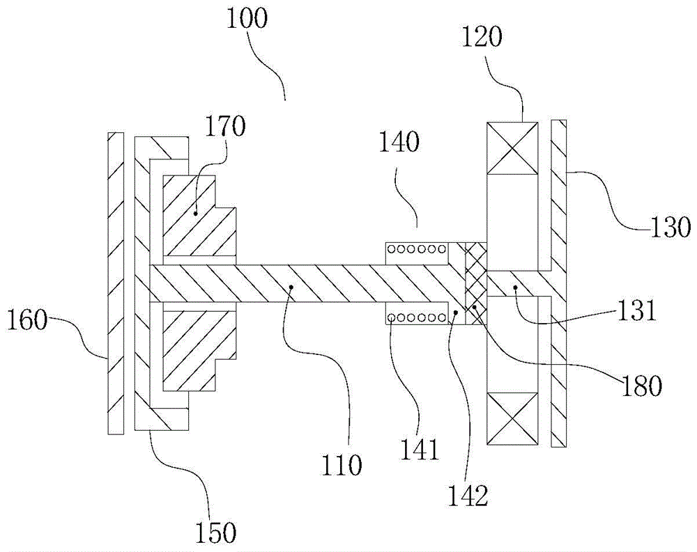
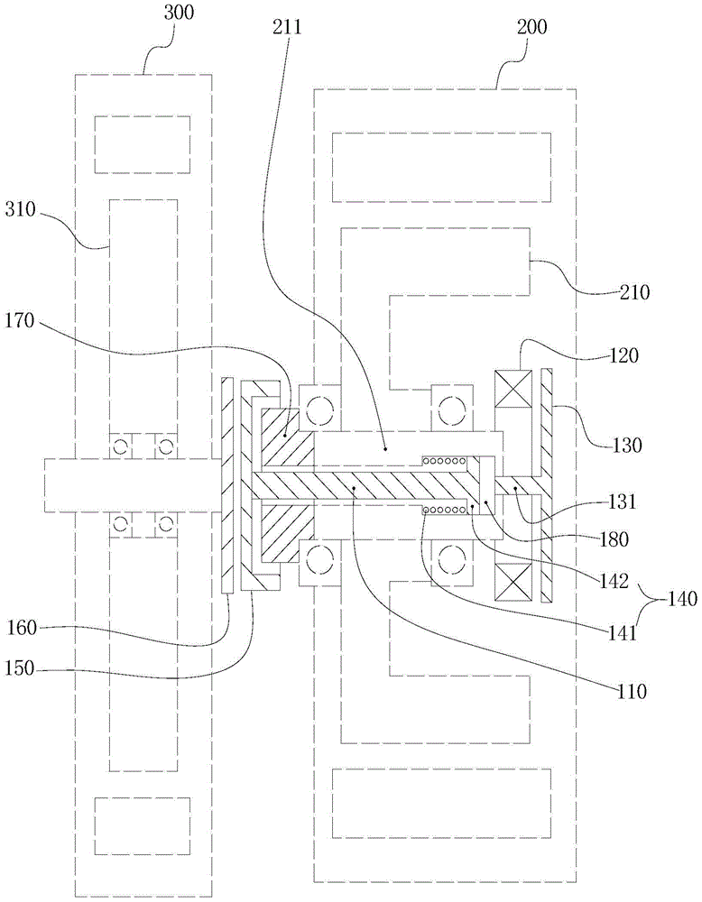
[0046] see figure 1 with figure 2 , this embodiment discloses an electromagnetic tooth clutch 100, which is used to realize the driving clutch of the first motor 300 and the second motor 200, the clutch includes a joystick 110, a ring electromagnet 120, an armature 130 and an elastic reset mechanism 140 , and includes a matching movable face gear 150 and a fixed face gear 160 . In order to show the positional relationship of each member of the clutch of the present invention more clearly, to show the difference in structure and effect between it and the existing clutch, figure 2 The first motor 300 and the second motor 200 are shown in dashed lines, the first motor 300 includes the rotor 310 of the first motor, the second motor 200 includes the rotor 210 of the second motor, and the rotor 210 of the second motor includes Shaft 211. In the following description of this embodiment, the structural relationship between the c...
Embodiment 2
[0055] Embodiment 2 Dual-motor hybrid power system
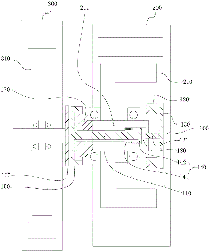
[0056] see image 3 , the present invention provides a dual-motor hybrid power system, the system includes a first motor 300 and a second motor 200, and includes the electromagnetic dog clutch 100 of Embodiment 1, and the technical solution described in Embodiment 1 also belongs to this Embodiment, Embodiment 1 The scheme that has been described will not be described again.
[0057] The electromagnetic dog clutch 100 is disposed between the first motor 300 and the second motor 200 , and is used to realize the drive clutch of the first motor 300 and the second motor 200 .
[0058] It can be seen from the description of the first embodiment that the joystick 110 and the elastic return mechanism 140 are located in the inner cavity of the rotor 210 of the second motor, and the armature 130 and the ring electromagnet 120 are located in the second motor The outer side of the rotor 210, that is, away from the first motor 300; the...
Embodiment 3
[0059] Embodiment 3 Dual-motor hybrid power system
[0060] see Figure 4 with Figure 5 , this embodiment also provides a dual-motor hybrid system, which is a further improvement on the basis of Embodiment 2. The technical solution disclosed in Embodiment 2 also belongs to this embodiment. The technology described in Embodiment 2 The scheme will not be described repeatedly. Figure 4 In , the solid line represents the transmission of mechanical force, and the dashed line represents the transmission of electric power.
[0061]Specifically, on the basis of the technical solution described in the second embodiment, that is, on the basis that the second motor 200 realizes the driving and clutching of the first motor 300 through the electromagnetic dog clutch 100, the The dual-motor hybrid system further includes an engine 400 , a first motor driver 500 , a second motor driver 600 and an energy storage device 700 . The engine 400 is coupled to the first electric motor 300 by m...
PUM
 Abstract
Description
Claims
Application Information
 - Generate Ideas
- Intellectual Property
- Life Sciences
- Materials
- Tech Scout
- Unparalleled Data Quality
- Higher Quality Content
- 60% Fewer Hallucinations
Browse by: Latest US Patents, China's latest patents, Technical Efficacy Thesaurus, Application Domain, Technology Topic, Popular Technical Reports.
© 2025 PatSnap. All rights reserved.Legal|Privacy policy|Modern Slavery Act Transparency Statement|Sitemap|About US| Contact US: help@patsnap.com


