
Dust removal device of automatic sock knitter

A technology for a dust removal device and a sock machine, which is applied in the mechanical field, can solve problems such as no substantive technical solutions are proposed, and achieve the effects of increasing positioning stability, large contact area, and convenient disassembly.

Inactive Publication Date: 2014-12-10
刘杰
View PDF6 Cites 17 Cited by
  • Summary
  • Abstract
  • Description
  • Claims
  • Application Information

AI Technical Summary

Problems solved by technology

As for how to integrate the two functions of vacuuming and dust removal, it does not propose a substantive technical solution

Method used


Image

  • Dust removal device of automatic sock knitter
  • Dust removal device of automatic sock knitter
  • Dust removal device of automatic sock knitter

Examples


Embodiment Construction

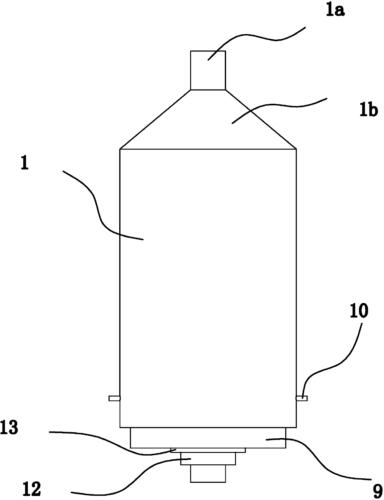
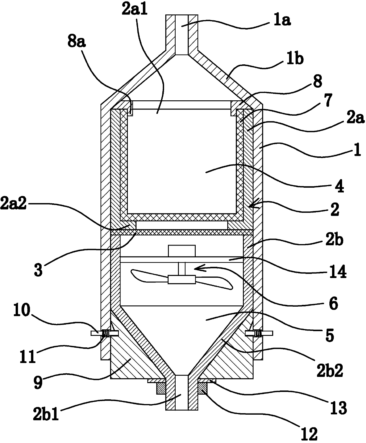
[0046] like figure 1 As shown, the dedusting device in the automatic hosiery spinning machine includes a dedusting cylinder connected to the frame of the knitting machine, and the dedusting cylinder includes an outer cylinder body 1 and an inner cylinder body 2 with a cavity inside.

[0047] like figure 1 and figure 2 As shown, the upper end of the inner cylinder 2 has an inlet 2a1, the lower end of the inner cylinder 2 has an outlet 2b1, the inner cylinder 2b1 is connected with a filter screen 3, and the filter screen 3 divides the inner cylinder into two adjacent cavities up and down : Upper chamber 4 and lower chamber 5. The inlet 2a1 is located at the upper cavity 4, and the outlet 2b1 is located at the lower cavity 5. The lower cavity 5 is also connected with a fan 6 that enables the airflow from the upper cavity 4 to enter the lower cavity 5. The top of the outer cylinder 1 has a The connecting port 1a communicated with the inlet 2a1 has a positioning mechanism betwe...


PUM


Abstract

The invention provides a dust removal device of an automatic sock knitter, belonging to the technical field of machines. The dust removal device of the automatic sock knitter comprises a dust removal cylinder, wherein the dust removal cylinder is connected to a knitter rack; the dust removal cylinder comprises an outer cylinder body and an inner cylinder body; the inner parts of the outer cylinder body and the inner cylinder body are cavities; an inlet is formed in the upper end of the inner cylinder body; an outlet is formed in the lower end of the inner cylinder body; the inner cylinder body is internally connected with a filter screen; the filter screen is used for separating the inner cylinder body into an upper cavity and a lower cavity which are adjacent with each other; the inlet is formed in the upper cavity; the outlet is formed in the lower cavity; the lower cavity is also connected with a fan capable of enabling airflow in the upper cavity to flow into the lower cavity; a connection hole communicated with the inlet is formed in the top part of the outer cylinder body; a positioning mechanism capable of positioning the outer cylinder body and the inner cylinder body together is arranged between the outer cylinder body and the inner cylinder body. The dust removal device of the automatic sock knitter is good in dust removal effect and compact in structure.

Description

technical field [0001] The invention belongs to the technical field of machinery, and relates to a sock spinning machine capable of automatically spinning socks, in particular to a dust removal device in the automatic sock spinning machine. Background technique [0002] During the operation of the automatic sock spinning machine, small pieces of fiber will be generated. In order to reduce pollution and improve the quality of the working environment, the existing automatic sock spinning machine usually has a dust removal device that can absorb the above-mentioned small pieces of fiber. [0003] Existing dust removal equipment usually adopts large-scale industrial dust removal equipment, and the same dust removal equipment is connected to multiple automatic sock spinning machines at the same time. During the working process of the dust removal equipment, dust removal is carried out on multiple sock spinning machines at the same time. [0004] However, in the industrial produc...

Claims


Application Information

Patent Timeline
Patent Type & Authority Applications(China)
IPC IPC(8): B01D46/00B01D46/10B01D46/24B01D46/42D04B35/32
Inventor 王永生
Owner 刘杰
Learn More