Touch control display panel and touch control display device

A touch display panel and touch display device technology, which is applied in the direction of instruments, electrical digital data processing, and data processing input/output process, can solve the problems of high resistance value dependence and high resistance-capacitance load, and improve the overall performance, increased sensitivity, and the effects of increased layout area

Active Publication Date: 2014-12-03
INNOLUX CORP
View PDF9 Cites 11 Cited by
  • Summary
  • Abstract
  • Description
  • Claims
  • Application Information

AI Technical Summary

Problems solved by technology

But there are still some problems, such as high dependence on resistance value, high RC loading, etc.

Method used


Image

  • Touch control display panel and touch control display device
  • Touch control display panel and touch control display device
  • Touch control display panel and touch control display device

Examples


Embodiment Construction

[0048] A touch display panel and a touch display device according to preferred embodiments of the present invention will be described below with reference to related drawings, wherein the same elements will be described with the same reference symbols. In addition, the illustrations of all the implementation aspects of the present invention are only schematic, and do not represent actual dimensions and proportions.

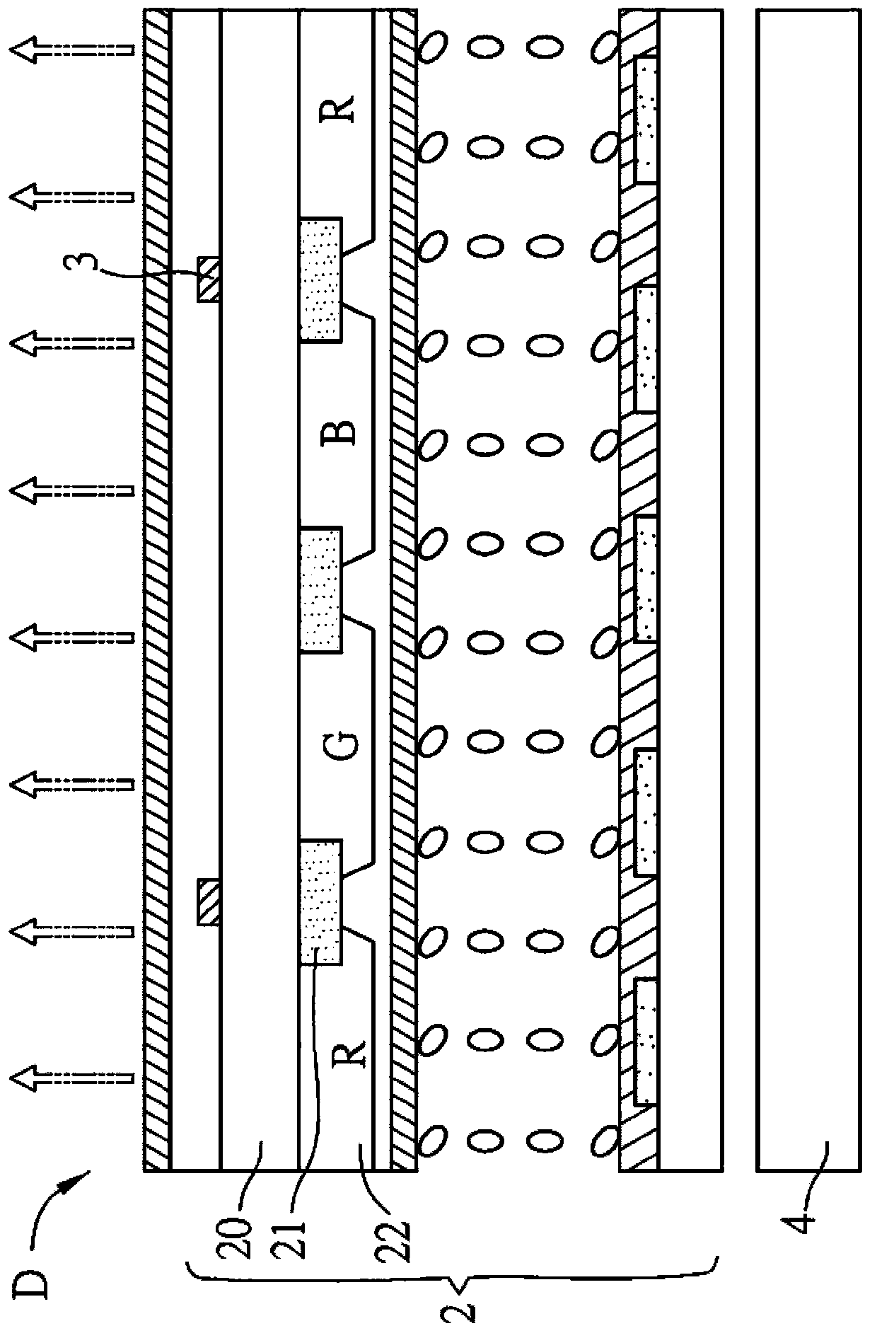
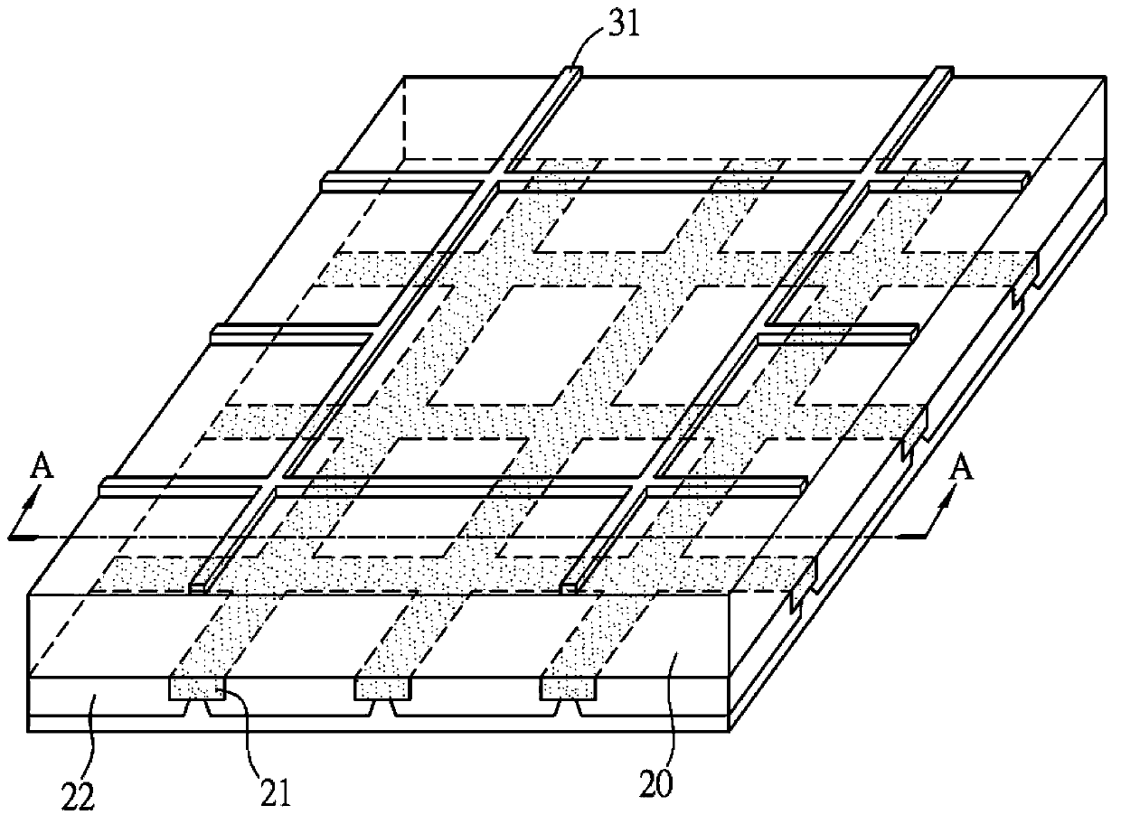
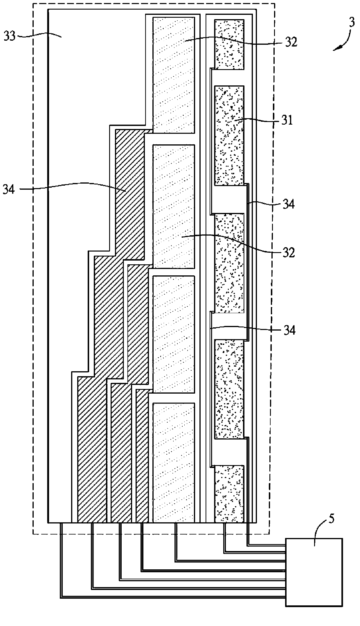
[0049] Please refer to figure 1 , figure 2 , Figure 3A and Figure 3B as shown, figure 1 is a schematic cross-sectional view of the touch display device of the present invention, figure 2 It is a partial perspective view of the touch display panel of the present invention. Figure 3A and Figure 3B It is a schematic diagram of the arrangement of sensing circuits in the touch display panel and a partial enlarged view thereof.

[0050] The touch display device D of the present invention includes a touch display panel 2 , a backlight module 4 and at least o...


PUM

PropertyMeasurementUnit
Line widthaaaaaaaaaa

Abstract

The invention relates to a touch control display panel, which comprises a substrate, a light shielding matrix layer and a sensing circuit, wherein the sensing circuit is positioned on one side surface of the substrate to form a single layer structure, is positioned in a vertical projection part of the light shielding matrix layer and comprises a plurality of driving electrodes, a plurality of sensing electrodes and a plurality of conducting wires, in addition, the driving electrodes and the sensing electrodes are mutually insulated and separated, and the conducting wires are respectively connected with each driving electrode and each sensing electrode, wherein the sensing electrodes, the driving electrodes and the conducting wires are all positioned in the single layer. The invention also discloses a touch control display device. The touch control display panel and the touch control display device provided by the invention have the advantages that under the condition of not increasing the light transmission loss, the distribution area of the sensing circuit can be increased, so that the goals of improving the sensitivity of the touch control display panel and the touch control display device, reducing the integral resistance-capacitance load and improving the integral efficiency are achieved.

Description

technical field [0001] The present invention relates to a touch display panel and a touch display device, in particular to a touch display panel and a touch display device in which the sensing circuit is located on the side of a substrate to form a single-layer structure. Background technique [0002] The touch technology applied to touch display panels can be roughly divided into two types: capacitive touch display panel and resistive touch display panel. In recent years, the market share of capacitive touch display panel has gradually grown, and it has the opportunity to surpass resistive touch display panel and become the market leader. mainstream technology. Capacitive sensing touch is to change the capacitance of the panel to cause a current change, which is then converted into a potential change to determine the user's touch coordinates. [0003] Among them, the capacitive touch display panel can be further subdivided into a single-layer capacitive touch display panel...

Claims


Application Information

Patent Timeline
IPC IPC(8): G06F3/044
Inventor 黄允中吴柏翰
Owner INNOLUX CORP
Why Eureka
Try Eureka