
Electro-spinning device for auxiliary inducing of batch manufacturing of diameter-controllable nano-fibers

A nanofiber and batch technology, which is applied in the field of nanofiber diameter-controlled assisted induction batch electrospinning device, can solve the problems of liquid droplets, uneven diameter of nanofibers, and low output, and achieve the effect of preventing the liquid level from being too high

Active Publication Date: 2014-12-03
XIAMEN UNIV
View PDF6 Cites 9 Cited by
  • Summary
  • Abstract
  • Description
  • Claims
  • Application Information

AI Technical Summary

Problems solved by technology

Such as blowing induced electrospinning (Y.Liu, J.H.He, et al, Biomimic fabrication of electrospun multiple nanofibers with high-throughput [J]. Chaos Solution and Fractals, 2008, 37, 643-651), using the induction effect of auxiliary airflow fibers Uniformity is improved, but this method has low yield, and the auxiliary gas flow control is difficult to ensure the stability of the process
Another example is that the Chinese patent CN200910235204 discloses a kind of electrospinning device for mass production of nanofibers, and the output is significantly improved, but verification experiments show that droplets are prone to appear, and the diameter of the prepared nanofibers is very uneven.

Method used


Image

  • Electro-spinning device for auxiliary inducing of batch manufacturing of diameter-controllable nano-fibers
  • Electro-spinning device for auxiliary inducing of batch manufacturing of diameter-controllable nano-fibers
  • Electro-spinning device for auxiliary inducing of batch manufacturing of diameter-controllable nano-fibers

Examples


Embodiment Construction

[0026] The following embodiments will further illustrate the structure and function of the present invention in conjunction with the accompanying drawings.

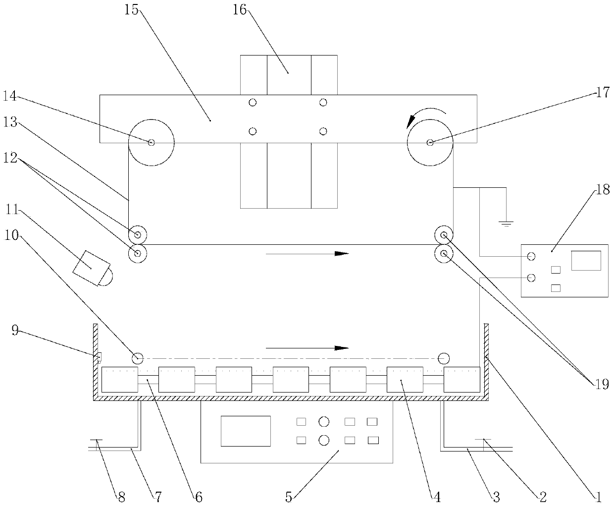
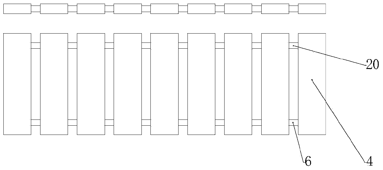
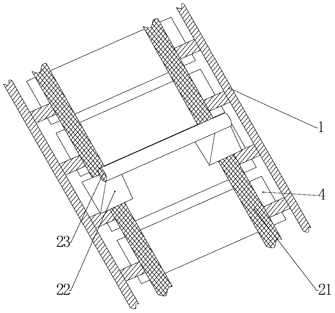
[0027] see Figure 1~5, the embodiment of the present invention is provided with solution tank 1, liquid outlet valve 2, liquid outlet pipe 3, fiber diameter control device, ultrasonic exciter 5, liquid inlet pipe 7, liquid inlet valve 8, ultrasonic liquid level sensor 9, auxiliary induction Device 10, industrial CCD high-definition image sensor 11, collection device, DC high voltage power supply 18. The fiber diameter control device is provided with an adjustment slider 4, a precision screw 6, and a polished rod guide rod 20; the auxiliary induction device 10 is provided with a linear guide rail 21, a slider 22, a slider connecting rod 23, and an installation base 24; Describe collection device feeding auxiliary rolling wheel 12, collecting plate 13, feeding roller 14, collecting device hanging plate 15, servo motor 16,...


PUM


Abstract

The invention discloses an electro-spinning device for auxiliary inducing of batch manufacturing of diameter-controllable nano-fibers, and relates to an electro-spinning device. The electro-spinning device comprises a solution trough, a liquid outlet valve, a fiber diameter control device, an ultrasonic vibration exciter, a liquid inlet pipeline, a liquid inlet valve, an ultrasonic liquid level sensor, auxiliary inducing devices, an industrial CCD image sensor and a collecting device, wherein the fiber diameter control device is provided with adjusting sliding blocks, precise screw rods and polish guide rods; each auxiliary inducing device is provided with linear guide rails, sliding blocks, a sliding block connecting rod and mounting bases; the collecting device is provided with auxiliary feeding rolling wheels, a collecting board, a feeding cylinder, a collecting device hanging board, a motor, a driving feed cylinder and feed auxiliary rolling wheels. According to the device, the ultrasonic vibration exciter is utilized to generate solution waves, and the auxiliary inducing device is utilized to perform jet flow injection control in a matching manner; intervals between polar plates are utilized to restrain a jet flow initial diameter and migration; the collecting device which can feed continuously and an auxiliary inducing process are utilized, and the image sensor is cooperatively used to recognize, so that the defects that the yield is low, the diameter distribution is large in difference, the bead-shaped structure is provided, and the nozzle is easy to block are overcome.

Description

technical field [0001] The invention relates to an electrospinning device, in particular to a nanofiber diameter-controlled assisted induction batch electrospinning device. Background technique [0002] Due to the excellent electrical, mechanical, optical properties and high specific surface area of ​​nanofibers, they are widely used in fields such as filtration, battery separators, and biological tissue engineering, and their market share in emerging fields such as electronics and energy is also increasing. rise, so it has a huge market prospect. [0003] Due to its own advantages, such as simple system, fast speed, low cost, continuous fiber, small and uniform diameter, etc., electrospinning technology has gradually become the main technology for preparing nanofibers. However, the traditional electrospinning technology usually uses a single needle as the spinneret, which is inefficient and the output is very low, so the electrospinning nanofiber batch device has become th...

Claims


Application Information

Patent Timeline
IPC IPC(8): D01D5/00D01D13/02
Inventor 柳娟卫瑾郑建毅郑高峰虞凌科占瞻王士虎孙道恒
Owner XIAMEN UNIV
Learn More