Retractable supporting structure and hospital bed lifting mechanism
A support structure and telescopic technology, applied in the direction of hospital beds, lifting frames, lifting devices, etc., can solve the problems of inconvenience for patients to get on and off the bed, reduce the patient's treatment experience, and the screw-driven support structure occupies a large space. The effect of reducing bulk, large reach
- Summary
- Abstract
- Description
- Claims
- Application Information
AI Technical Summary
Problems solved by technology
Method used
Image
Examples
Embodiment 1
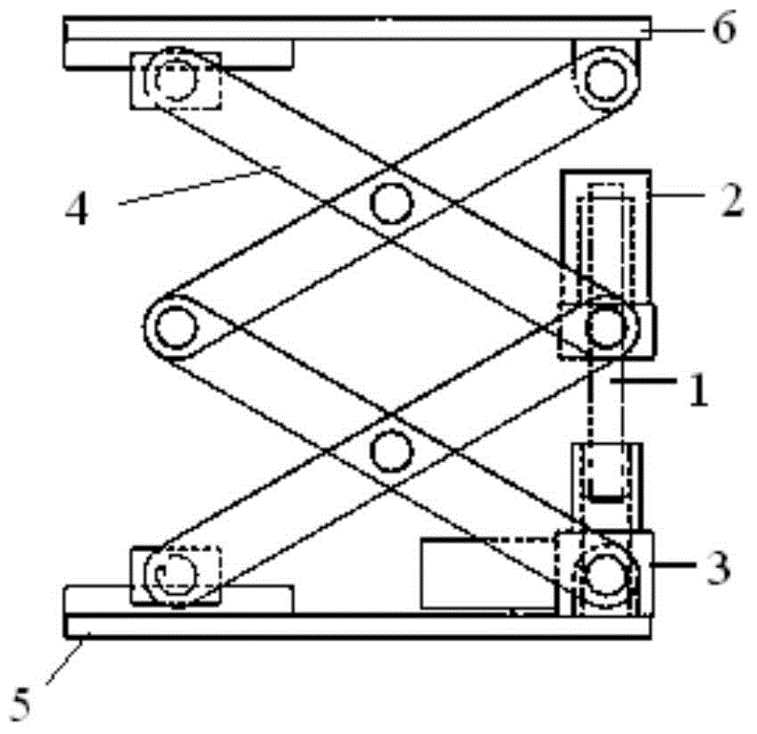
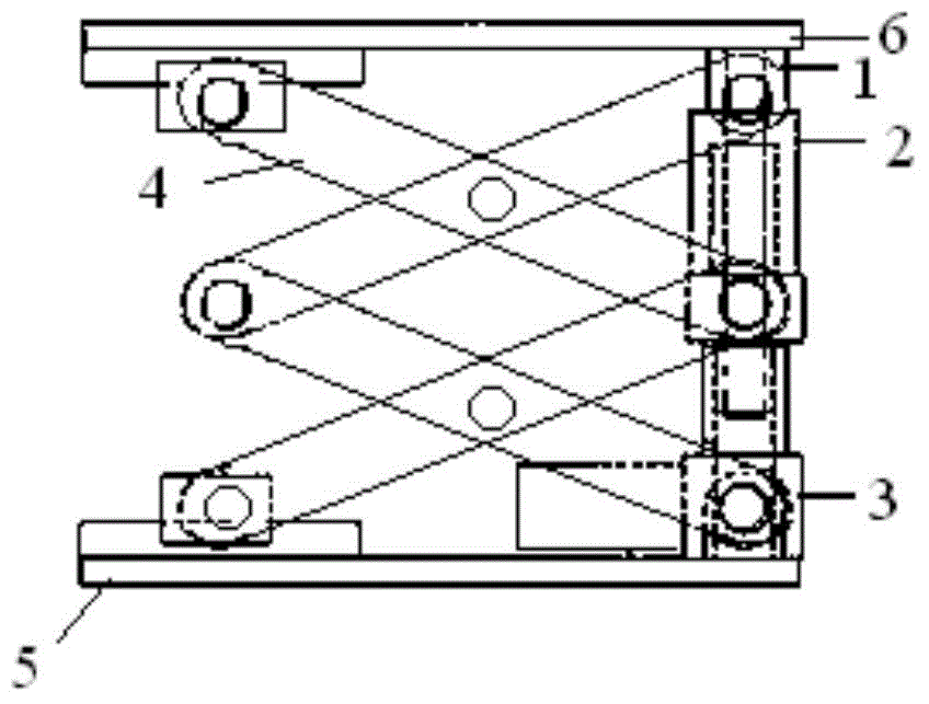
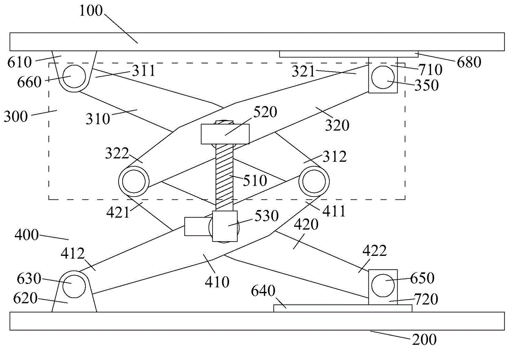
[0052] Figure 3 ~ Figure 6 It is a structural schematic diagram of the telescopic support structure provided by this embodiment. in, image 3 It is a schematic diagram of the front structure after the expansion of the telescopic support structure; Figure 4 It is a schematic diagram of the back structure after the telescopic support structure is deployed; Figure 5 It is a schematic diagram of the rear structure of the telescopic support structure after contraction; Image 6 It is a schematic diagram of the front structure of the retractable support structure.
[0053] combined reference image 3 with Figure 4 As shown, the telescopic support structure provided by this embodiment includes: a telescopic bracket and a screw drive mechanism. The telescopic bracket is composed of multiple groups of scissor brackets, and the multiple groups of scissor brackets are arranged along the first direction. Wherein, one group of scissors brackets includes two poles, the two poles ...
Embodiment 2
[0082] The technical solution provided by this embodiment and embodiment 1 is roughly the same, refer to Figure 10 As shown, the telescopic support structure provided by this embodiment includes a scissors support 300 and a scissors support 900 .
[0083] Compared with the telescopic support structure in Embodiment 1, the difference lies in that the scissors support 900 includes two struts 910 and 920 that are articulated crosswise. The lower end 912 of the pole 910 is movably connected with the base 620, and the upper end 911 is movably connected with the lower end 312 of the pole 310 of the scissors support 300; the lower end 922 of the pole 920 is movably connected with the slider 720, and the upper end 921 It is flexibly connected with the lower end 322 of the pole 320 of the scissors support 300 . Moreover, the cross connection point of the struts 910 and 920 is located in the middle of the struts 910 and 920 .
[0084] The structure of the scissors support 300 is simi...
PUM
 Abstract
Description
Claims
Application Information
 - R&D
- Intellectual Property
- Life Sciences
- Materials
- Tech Scout
- Unparalleled Data Quality
- Higher Quality Content
- 60% Fewer Hallucinations
Browse by: Latest US Patents, China's latest patents, Technical Efficacy Thesaurus, Application Domain, Technology Topic, Popular Technical Reports.
© 2025 PatSnap. All rights reserved.Legal|Privacy policy|Modern Slavery Act Transparency Statement|Sitemap|About US| Contact US: help@patsnap.com


