
Method for producing a machine element, and machine element for an electric machine

A technology of machine components, powder particles, used in the field of machine components of magnetic fields, and the field of manufacturing such machine components

Active Publication Date: 2014-11-19
ROBERT BOSCH GMBH
View PDF7 Cites 0 Cited by
  • Summary
  • Abstract
  • Description
  • Claims
  • Application Information

AI Technical Summary

Problems solved by technology

[0004] The disadvantage of the powder materials used is that one can thus only obtain machine elements with homogeneous magnetism in all spatial directions

Method used


Image

  • Method for producing a machine element, and machine element for an electric machine
  • Method for producing a machine element, and machine element for an electric machine
  • Method for producing a machine element, and machine element for an electric machine

Examples


Embodiment Construction

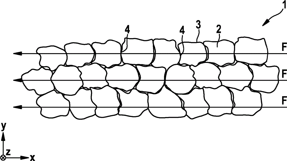
[0033] figure 1 A schematic cross-sectional view of a section of a machine element 1 made of SMC material is shown. The SMC material basically consists of powder particles 2 of the same size, the powder particles are made of magnetic material such as iron, the surfaces of the powder particles are insulated by an insulating layer 3 . The powder particles 2 have a diameter of about 0.1 mm and are roughly cuboidal or spherical in shape with irregularly shaped surfaces.

[0034] The particles 2 are pressed against each other during the pressing process in order to define the shape of the machine element 1 to be produced and subsequently hardened in a thermal process so that the powder particles are permanently connected to each other. figure 1 An exemplary arrangement of powder particles 2 after a thermal process is shown. One sees powder particles 2 of the same size, which lie against each other so that the area of ​​the interstices between the particles 2 is minimized as much ...


PUM


Abstract

The invention relates to a method for producing a machine element (1), in particular for a stator or a rotor of an electric machine, comprising the following steps: providing a magnetic powder material having elongated magnetic powder particles (12) in a mold; applying a magnetic field that penetrates the provided powder material; compressing the powder material in the mold (17); and connecting the powder particles in order to obtain the machine element (1).

Description

technical field [0001] The invention relates to a machine element for an electric machine, in particular for conducting a magnetic field for a stator or rotor of an electric machine. The invention also relates to a method for producing such machine elements. Background technique [0002] In addition to the chip structure of machine elements, it is also known to construct several machine elements for guiding magnetic fields, which are manufactured from soft magnetic composite (SMC) powder material, such as Somaloy 700, which is produced, for example, by "Somaloy Technology" ( Somaloy Booklet, October 2010, Hoganas GmbH, Switzerland, www.hoganas.com) publicly available. [0003] SMC materials consist of surface-insulated iron core particles that are not uniformly shaped but have a roughly spherical structure of the same size. The powder material has granules made of iron compounds of a size suitable for pressing and forming of machine elements. The particles can, for exampl...

Claims


Application Information

Patent Timeline
IPC IPC(8): H02K15/02H02K1/02
CPCH01F41/0246H02K2201/15H02K15/02H02K1/02
Inventor S.A.埃文斯
Owner ROBERT BOSCH GMBH
Learn More