
UHF RFID reader based on beam switching smart antenna

A beam switching and smart antenna technology, applied in the field of radio frequency identification, can solve the problems of limited effective identification area, difficult to achieve high-efficiency results, limited effective identification area of ​​passive RFID system, etc., and achieve anti-collision and positioning accuracy capabilities Improved effect

Inactive Publication Date: 2014-11-19
TIANJIN POLYTECHNIC UNIV
View PDF0 Cites 4 Cited by
  • Summary
  • Abstract
  • Description
  • Claims
  • Application Information

AI Technical Summary

Problems solved by technology

[0004] (1) In the passive UHF RFID system, the maximum recognition distance of a reader is about 10 meters, and the total effective recognition area is limited, which cannot meet the needs of most users
[0005] (2) In the passive UHF RFID system, a key problem is that it is difficult to achieve 100% recognition rate, that is, there are some tags that are not recognized, that is, the problem of missing tags
In terms of hardware, there are two main reasons for the problem of lost tags: First, the effective identification area of ​​passive RFID systems is limited because of the limited transmit power of the antenna and the fixed radiation pattern
Second, multipath interference causes some tags not to have enough energy to be activated in the identification area
However, it is difficult to achieve efficient results by simply relying on software-based anti-collision. If there is support from the antenna, anti-collision can be more effective
[0007] (4) Since the commonly used RFID reader antenna has a low-gain, wide-beam transmission pattern, the label positioning error is relatively large
If using a phased array antenna capable of producing multiple high-gain beams, EIRP can exceed 4W in a certain direction for a short period of time, and when calculating the average power, it has the same average power as a low-directivity, fixed-beam antenna, Average power is reduced because the beam is steered by sweeping in multiple directions

Method used


Image

  • UHF RFID reader based on beam switching smart antenna
  • UHF RFID reader based on beam switching smart antenna

Examples


Embodiment Construction

[0023] In order to make the object, technical solution and advantages of the present invention clearer, the embodiments of the present invention will be further described in detail below in conjunction with the accompanying drawings, but the embodiments of the present invention are not limited thereto.

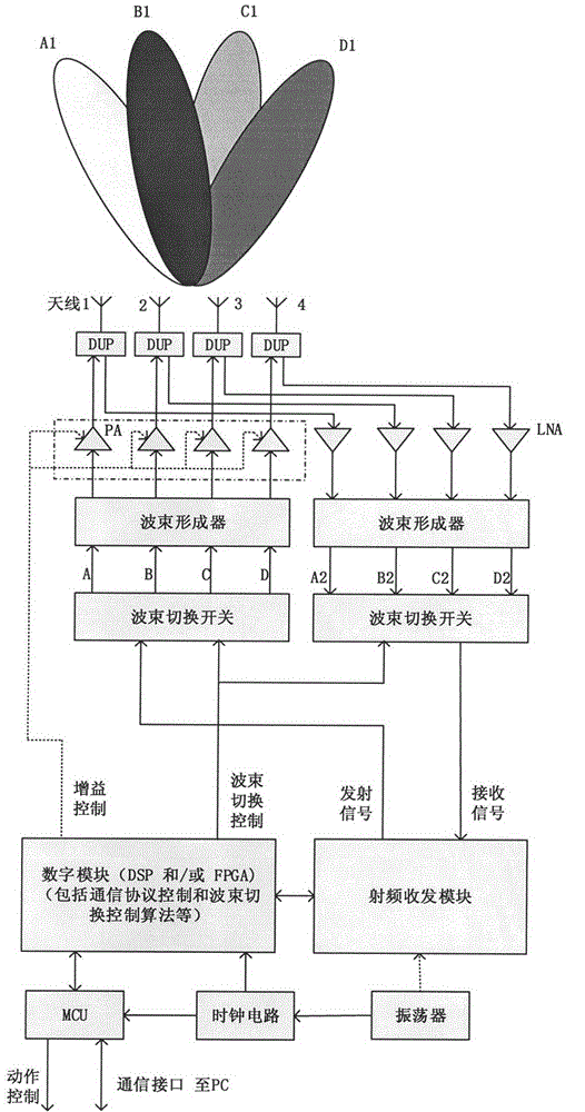
[0024] Such as figure 1 As shown, taking the formation of 4 fixed beams as an example to illustrate the UHF RFID reader based on the beam switching smart antenna. The invention includes a controller MCU, a digital module, a radio frequency transceiver module, a beam switching switch, a beamformer, a gain programmable power amplifier PA, a low noise amplifier LNA, a transceiver duplexer DUP and an antenna array.

[0025] When transmitting signals, the digital module controls the radio frequency transceiver module to generate radio frequency signals according to the instructions of the controller and the communication protocol. At the same time, the digital module selects one of...


PUM


Abstract

The invention discloses a UHF RFID reader based on a beam switching smart antenna and belongs to the technical field of radio frequency identification. The UHF RFID reader is characterized in that during signal transmitting, a digital module controls a radio-frequency transceiver module to produce a radio frequency signal according to commands and communication protocol of a controller, meanwhile, the digital module controls a beam change-over switch to switch corresponding channels of a beam former according to the beam switching control algorithm, the radio frequency signal generates an output signal of which the phase difference conforms to a certain rule after passing through the beam former, and the output signal is amplified by a power amplifier and then fed into an antenna array through a transmit-receive duplexer. The gains of all power amplifiers are controlled by the digital module. Electromagnetic waves radiated by antenna array elements are stacked in the space to form a high-gain narrow beam. During signal receiving, the process is opposite to that during signal transmitting. According to the invention, the maximal read-write distance, the effective recognition zone, the collision resistance, the positioning accuracy and the like are all improved.

Description

technical field [0001] The present invention relates to a radio frequency identification (RFID) technology, in particular to a UHF RFID reader Background technique [0002] With the development of information technology, the Internet of Things has developed into a new industry. As one of the foundations of the Internet of Things, Radio Frequency Identification (RFID) technology has become a technology that people pay more and more attention to. The RFID system is mainly composed of three parts: transponder (radio frequency card and electronic tag), reader (reader and base station) and host computer system (middleware and network application). In the radio frequency identification system, according to the different structures of the electronic tag power supply system, RFID electronic tags are mainly divided into active tags, semi-active tags and passive tags. Active tags and semi-active tags have an external battery, which provides energy for the work of the tag chip. The ad...

Claims


Application Information

Patent Timeline
Patent Type & Authority Applications(China)
IPC IPC(8): G06K7/00
Inventor 李建雄陈晓宇聂海
Owner TIANJIN POLYTECHNIC UNIV
Learn More