
Rear part visualization detection apparatus for wearing of shield machine cutter and method thereof

A shield machine tool and detection device technology, which is applied in the direction of measuring devices, optical devices, and material analysis through optical means, can solve the problem of inability to accurately predict tool wear, inability to detect eccentric wear and abnormal wear, and affecting tunnels. The safety of surrounding buildings and other issues can be achieved to maximize construction and operation benefits, reduce project safety risks, and achieve important economic and social benefits.

Inactive Publication Date: 2014-11-19
CCCC TUNNEL ENG +1
View PDF6 Cites 13 Cited by
  • Summary
  • Abstract
  • Description
  • Claims
  • Application Information

AI Technical Summary

Problems solved by technology

Among the above methods, the method of opening the cabin for inspection is the most direct and effective, but it has a high risk, which may cause the collapse of the excavation surface, thereby affecting the safety of the buildings around the tunnel, and the cycle is long and the cost is high
The tool wear sensing device can only be installed on a small number of tools, and cannot sense the wear of other tools, and cannot detect partial wear and abnormal wear
Odor Additives Not Effective in EPB Shields and Slurry Shields
The tunneling parameter analysis method is to establish an empirical relationship after analyzing some of the most basic and important tunneling data, which cannot accurately predict the wear of the tool

Method used

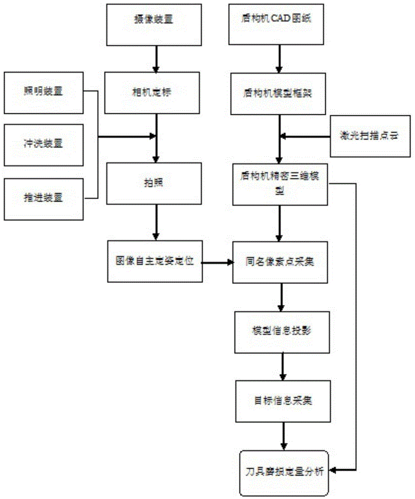

Image

  • Rear part visualization detection apparatus for wearing of shield machine cutter and method thereof
  • Rear part visualization detection apparatus for wearing of shield machine cutter and method thereof
  • Rear part visualization detection apparatus for wearing of shield machine cutter and method thereof

Examples


Embodiment Construction

[0026] The present invention will be further described below in conjunction with the accompanying drawings and specific embodiments.

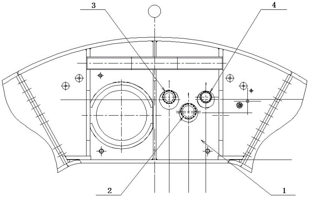
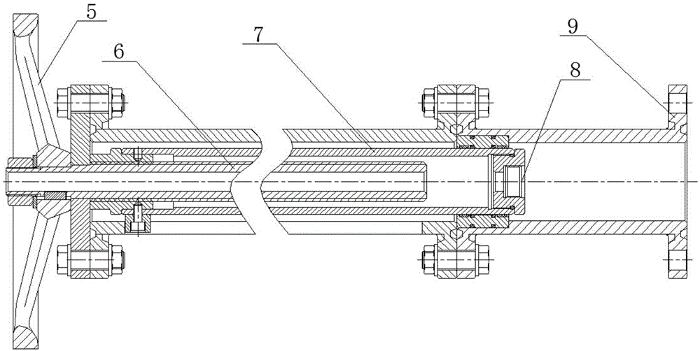
[0027] like figure 2 In the described embodiment, a rear visual detection device for shield machine tool wear includes a camera device 2, an illumination device 3, a flushing device 4, a first propulsion device, a second propulsion device, a data acquisition and analysis device and The bubble chamber 1 of the shield machine. There are three round holes on the front wall of the bubble chamber 1 of the shield machine. The round holes are welded with ball joints and ball valves are respectively installed for connecting the camera device 2, the lighting device 3 and the washing device 4. The first propulsion The device is respectively threaded with the camera device 2 and the lighting device 3, the second propulsion device is threaded with the flushing device 4, the camera device 2 is connected with the data acquisition and analysis device, and bo...


PUM


Abstract

The invention discloses a rear part visualization detection apparatus with characteristics of safety, convenience, economy and reliability for wearing of a shield machine cutter and a method thereof. The rear part visualization detection apparatus for wearing of the shield machine cutter comprises a camera device, a lighting device, a slushing apparatus, a first propulsion apparatus, a second propulsion apparatus, a data acquisition and analysis device, and a shield machine bubble cabin, three circular holes are arranged on the front wall of the shield machine bubble cabin, the circular holes are welded with a spherical hinge and respectively install with a ball valve for connecting the camera device, the lighting device and the slushing apparatus, the first propulsion apparatus is respectively connected to the camera device and the lighting device in a threaded mode, the second propulsion apparatus and the slushing apparatus are connected in the threaded mode, the camera device is connected to the data acquisition and analysis device, and the first propulsion apparatus and the second propulsion apparatus are connected to the front wall of the shield machine bubble cabin through a ball valve. The rear part visualization detection apparatus has the beneficial effect that the large area damage due to late replacement of the cutter after being damaged, or unnecessary cabin opening for inspection and cutter replacement can be avoided, cutter service life is prolonged, engineering safety risk is reduced, and engineering period is shortened.

Description

technical field [0001] The invention relates to the related technical field of shield machine tool wear detection, in particular to a rear visual detection device and method for shield machine tool wear in tunnel shield construction. Background technique [0002] Tunnel shield construction has been widely used in soft soil areas due to its advantages of economy, safety and less impact on the ground environment. In the process of shield tunneling, the evaluation and solution of tool wear is one of the most difficult topics. In the shield engineering of composite strata, the shield machine generally uses a composite cutter head, that is, the hob and the scraper are matched with each other, the scraper is protected by the hob, and the wear of the shield machine tool is mainly the wear of the hob. The wear of the hob can generally be divided into normal wear and abnormal wear. Normal wear mainly refers to uniform wear and partial wear, while abnormal wear mainly includes oil le...

Claims


Application Information

Patent Timeline
Patent Type & Authority Applications(China)
IPC IPC(8): G01N21/84G01B11/24
Inventor 石新栋吴全立石振明姚占虎赵小鹏管圣功游光文张英明王善高张亚果陈方伟俞松波
Owner CCCC TUNNEL ENG
Learn More