Electric connector and method for installing same on substrate

A technology for electrical connectors and installation directions, which is applied in the direction of connection, connection part protection grounding/shielding device, fixed connection, etc., which can solve the problems of increasing the cost of the shielding part, failing to achieve electrical connection, and increasing the thickness of the shielding part

Inactive Publication Date: 2014-11-12
FRAMATOME CONNECTORS INT SA
View PDF0 Cites 3 Cited by
  • Summary
  • Abstract
  • Description
  • Claims
  • Application Information

AI Technical Summary

Problems solved by technology

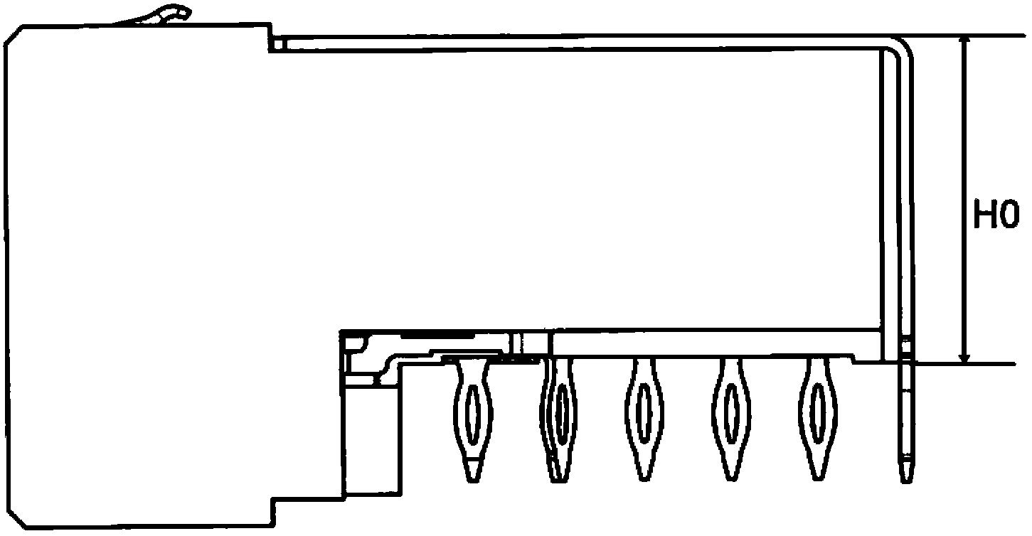
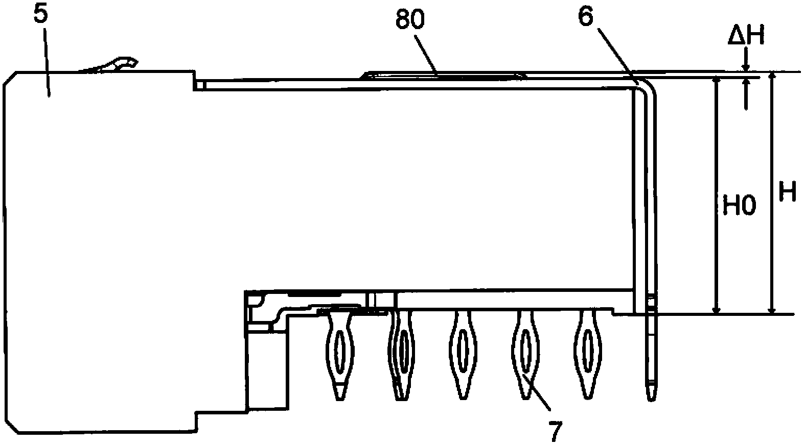
When an electrical connector with a small height needs to be press-fitted onto a printed circuit board, since the height of the electrical connector is less than the distance between the limit position of the pressing surface of the pressing tool and the surface of the substrate, the electrical contact of the electrical connector The head cannot be depressed a sufficient distance, electrical communication between the electrical contacts of the electrical connector and the electrical traces of the substrate cannot be achieved or the electrical communication is not reliable, or the electrical connector cannot be reliably fixed to the substrate
[0007] There are currently two ways to solve the above problems, one is to increase the height of the entire electrical connector housing, which greatly increases the material required for manufacturing the housing, and accordingly increases the manufacturing cost of the electrical connector housing; the other is to increase the height of the entire electrical connector housing. The method is to increase the thickness of the shield. Similarly, the material required to manufacture the shield is greatly increased, increasing the cost of the shield

Method used


Image

  • Electric connector and method for installing same on substrate
  • Electric connector and method for installing same on substrate
  • Electric connector and method for installing same on substrate

Examples


Embodiment Construction

[0041] Preferred embodiments according to the present invention are described below with reference to the accompanying drawings.

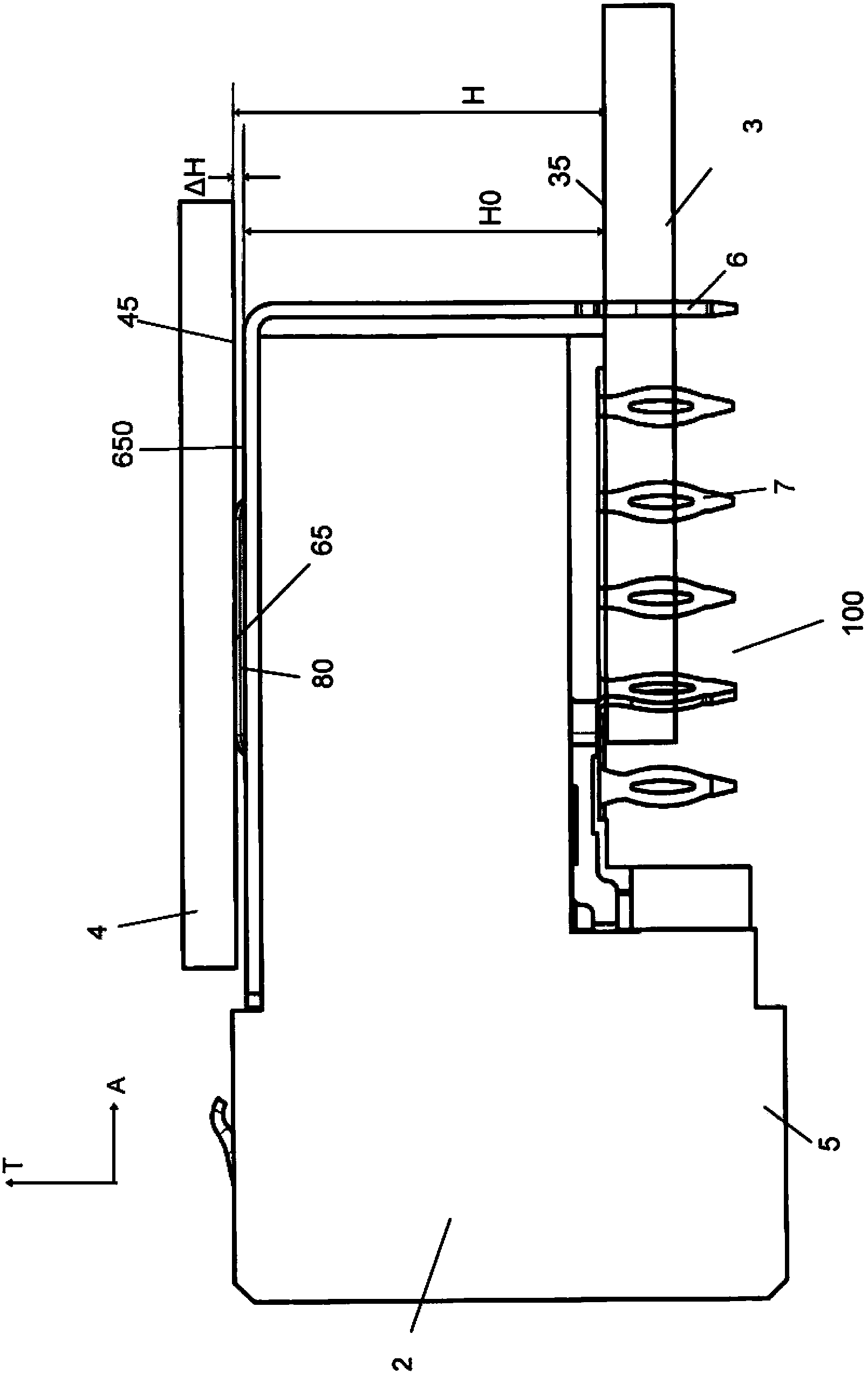
[0042] refer to figure 2 , shows an electrical connector system 100 comprising an electrical connector 2 and a substrate, which may be provided, for example, as a printed circuit board (PCB) 3 , figure 2 A state in which the electrical connector 2 is mounted to the printed circuit board 3 is shown in . The figure also shows a pressing tool 4 for installing the electrical connector 2 on the printed circuit board 3 .

[0043] In this embodiment, the electrical connector 2 is a right-angle electrical connector. image 3 show figure 2 A perspective view of the electrical connector 2 of the electrical connector system 100. The electrical connector 2 defines a mating interface 22 and a mounting interface 24 . The mating interface 22 is configured to cooperate with a mating electrical component, such as another electrical connector or other electric...


PUM


Abstract

The invention provides an electric connector used for being installed on a printed circuit board. The electric connector comprises a shell, a plurality electric contacts supported by the shell and a shielding element. Each electric contact is provided with a matching end and an installation end in a defined mode, wherein the matching ends are used for being connected to the other electric component, and the installation ends are used for being installed on the printed circuit board in the installation direction. The shielding element is installed on the shell and provided with an upper surface and one or more protrusions, wherein the upper surface faces the reverse direction opposite to the installation direction, the protrusions are arranged on the upper surface and protrude in the reverse direction, and when the electric connector is installed on the printed circuit board in an inserted mode in the installation direction, the protrusions are pushed by the pushing surface of a press fitting tool in an abutting mode. The invention further provides a method for installing the electric connector on the printed circuit board.

Description

technical field [0001] The present application generally relates to the field of electrical connectors, particularly electrical connectors mounted to a substrate such as a printed circuit board, the height of which is increased by providing one or more raised risers. Background technique [0002] Typically, an electrical connector is used to make an electrical connection between two electrical components, such as a first electrical component and a second electrical component. Here the first and second electrical components may be electrical connectors, cables, substrates such as printed circuit boards or the like. [0003] An electrical connector typically includes an electrical connector housing and a plurality of electrical contacts supported by the electrical connector housing. The connection of an electrical connector to a substrate, such as a printed circuit board, is generally accomplished by connecting the electrical contacts of the electrical connector to electrical...

Claims


Application Information

Patent Timeline
IPC IPC(8): H01R13/648H01R12/51H01R43/00
Inventor 詹涛鲁向前张宏图
Owner FRAMATOME CONNECTORS INT SA
Why Eureka
Try Eureka