


Quick Research
Generate reliable direction feasibility study reports for your R&D in just a few steps.

Technical Q&A
Discover and master advanced knowledge NOW. Basics, ideas, possibilities, all at once.

Find Solutions
As an expert in R&D theories, this can generate solutions to your technical problems instantly.

Evaluate Feasibility
Analyze your overall solution with one click, know your potential R&D risks in advance.

Monitor Landscape
Get weekly tech updates, stay abreast of the latest tech innovations and key insights.
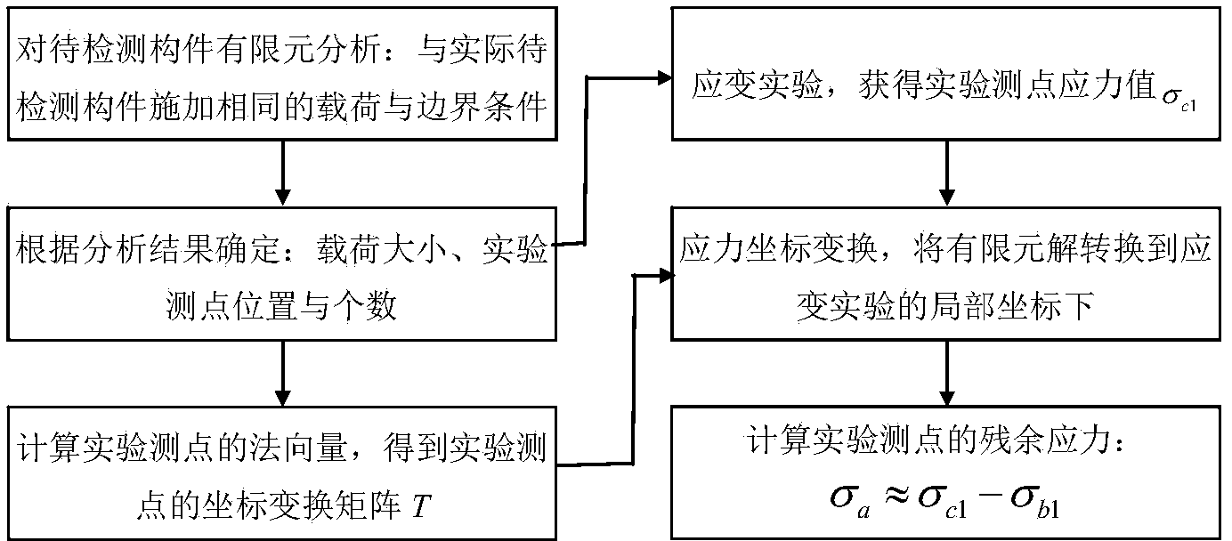
Load measurement-based residual stress detection method
A technology of residual stress and detection method, applied in the field of detection, can solve problems such as destructiveness and unsatisfactory effect, and achieve the effect of convenient application
- Summary
- Abstract
- Description
- Claims
- Application Information
AI Technical Summary
Problems solved by technology
Method used
Image

Examples
Embodiment approach 1
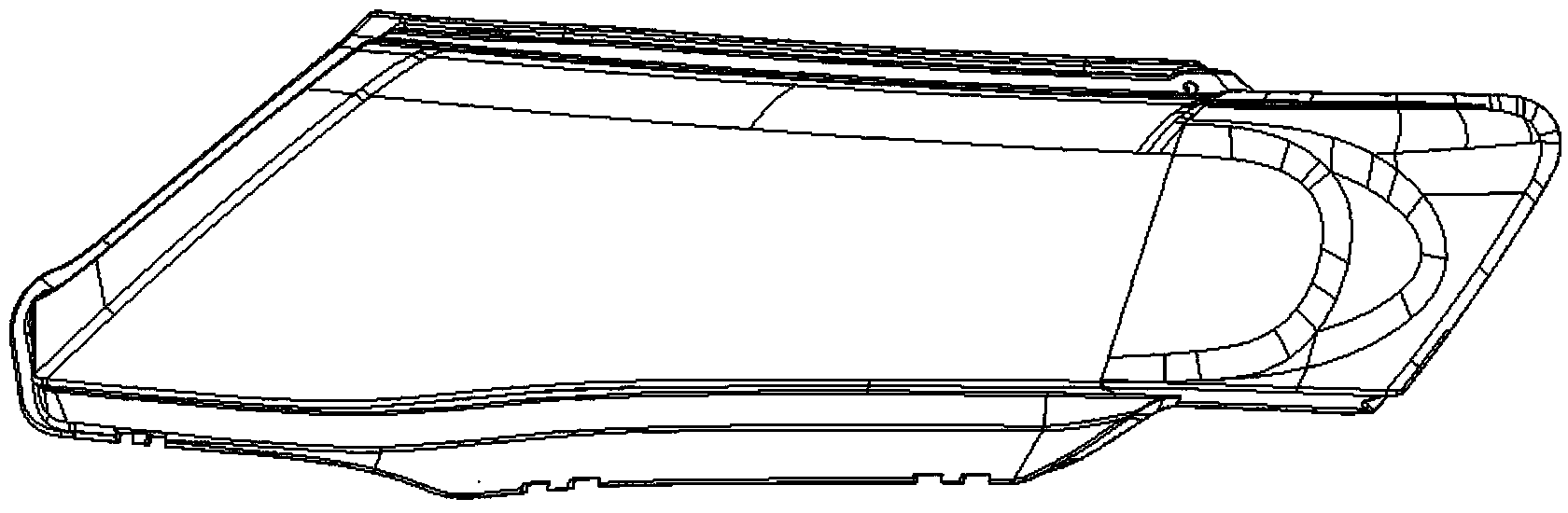
[0075] Such as image 3 As shown, the present invention provides an example of residual stress detection applied to injection molded products, which is characterized in that the injection molded parts have residual stress, so the detection method provided by the present invention is used for detection and calculation.
[0076] According to the basic steps provided by the present invention, the international system of units SI (basic dimension: mm, kg, s) is adopted, and the specific operation steps are as follows:
[0077] ① Determine the position of the loading point of the component to be tested, calculate and read the finite element solution σ' b1 .
[0078] Establish a computer geometric model for this application example product, and determine a pair of concentrated forces with a size of 20N, a direction perpendicular to the tangent plane of the loading point, and positions at points P1 and P2 through the debugging of loading calculations. The constraints are to impose ...
PUM
 Abstract
Description
Claims
Application Information
 - R&D Engineer
- R&D Manager
- IP Professional
- Industry Leading Data Capabilities
- Powerful AI technology
- Patent DNA Extraction
Browse by: Latest US Patents, China's latest patents, Technical Efficacy Thesaurus, Application Domain, Technology Topic, Popular Technical Reports.
© 2024 PatSnap. All rights reserved.Legal|Privacy policy|Modern Slavery Act Transparency Statement|Sitemap|About US| Contact US: help@patsnap.com