Eureka AIR delivers breakthrough ideas for toughest innovation challenges, trusted by R&D personnel around the world.

A gas flameless combustion device and combustion method with extremely low nitrogen oxide emissions

A nitrogen oxide, flameless combustion technology, applied in combustion methods, gas fuel burners, burners, etc., can solve the problems of poor combustion stability, long preheating time, insufficient consideration, etc., to improve combustion stability and The effect of safety, simple structure and low manufacturing cost

Active Publication Date: 2016-06-29
PEKING UNIV
View PDF6 Cites 1 Cited by
  • Summary
  • Abstract
  • Description
  • Claims
  • Application Information

AI Technical Summary

Problems solved by technology

[0004] In general, there are three problems in existing burners designed and developed based on flameless combustion technology: 1. Most of the designs of existing flameless burners are non-premixed, and laboratory tests and existing industrial applications show that , its nitrogen oxide emission is generally 30-50ppm, and it has not achieved the "optimal" flameless combustion technology in terms of nitrogen oxide emission reduction, and there is still room for improvement from "zero nitrogen oxide emission".
2. The design of existing flameless burners does not consider meeting the requirements of different gases for premixed / non-premixed combustion modes
3. The existing design of the flameless burner does not take enough consideration in satisfying the preheating of the furnace, or the combustion stability is poor, or the preheating time is too long, etc.

Method used


Image

  • A gas flameless combustion device and combustion method with extremely low nitrogen oxide emissions
  • A gas flameless combustion device and combustion method with extremely low nitrogen oxide emissions
  • A gas flameless combustion device and combustion method with extremely low nitrogen oxide emissions

Examples


Embodiment Construction

[0019] The present invention will be described in detail below in conjunction with the accompanying drawings and embodiments.

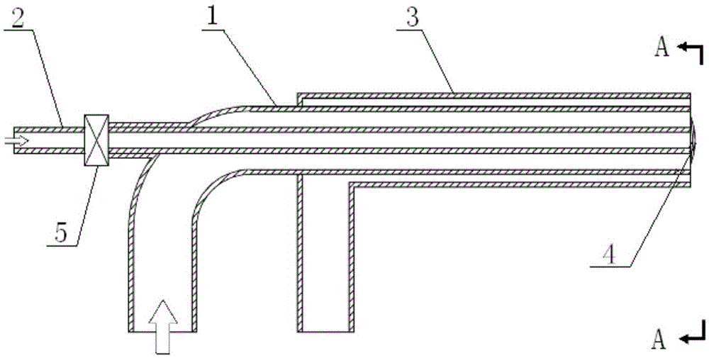
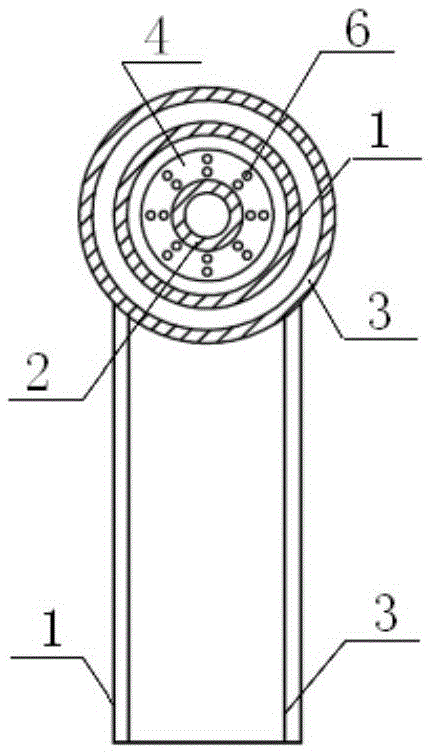
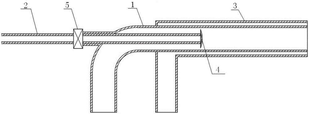
[0020] like figure 1 , figure 2 As shown, the present invention includes an air nozzle 1, a central gas nozzle 2, an outer gas nozzle 3 and a flame stabilizer 4.

[0021] The air nozzle 1 is an L-shaped pipe, one section of the L-shaped pipe is arranged horizontally, the end of the horizontal section of the L-shaped pipe is the outlet of the nozzle, and the other end of the L-shaped pipe is an air inlet; There is a horizontal branch 11.

[0022] The central gas nozzle 2 is a straight pipe, which passes through the horizontal branch pipe 11 and stretches into the horizontal section of the air nozzle 1 in parallel. An annular gap is left between the air nozzle 1 and the central gas nozzle 2 to form an air passage. The central gas nozzle 2 is connected with the horizontal branch pipe 11 through a sealing joint 5, and the sealing joint 5 has the funct...


PUM


Abstract

The invention relates to a gas flameless combustion device and combustion method with extremely low emission of nitrogen oxides, which comprises: an L-shaped air nozzle, one section of the air nozzle is arranged horizontally, and the end of the horizontal section of the air nozzle It is the outlet of the nozzle, and a horizontal branch pipe is arranged at the bend of the L-shaped pipe; a central gas nozzle is a straight pipe, which extends into the horizontal section of the air nozzle in parallel after passing through the horizontal branch pipe. An annular gap is left between the pipe and the central gas nozzle to form an air channel; the central gas nozzle is connected to the horizontal branch pipe through a sealed joint; an outer gas nozzle is sleeved and sealed connected to the air nozzle On the outside of the horizontal section, a nozzle inlet is arranged on one side of the outer gas nozzle, and an annular gap is left between the outer gas nozzle and the air nozzle to form an outer gas passage; the horizontal section of the outer gas nozzle, the air nozzle and the The three central gas nozzles have a coaxial relationship, and the outlet of the outer gas nozzle is flush with the end face of the outlet of the air nozzle; the flame stabilizer is installed at the outlet end of the central gas nozzle.

Description

technical field [0001] The invention relates to a gas combustion device and a combustion method, in particular to a gas flameless combustion device and a combustion method with extremely low emission of nitrogen oxides. Background technique [0002] At present, the problem of global air pollution is becoming more and more serious, and acid rain and PM2.5 have become the main environmental problems in some big cities. Nitrogen oxides are one of the main culprits in the formation of PM2.5, which seriously affects people's life and health. In China, nitrogen oxide emission reduction has become an important environmental governance task. With the tightening of nitrogen oxide emission standards and the implementation of a series of measures such as coal-to-gas conversion of industrial boilers, it is increasingly important to develop new low-nitrogen combustion technologies suitable for gas. The traditional low-nitrogen combustion technology widely used in the industry mainly in...

Claims


Application Information

Patent Timeline
Patent Type & Authority Patents(China)
IPC IPC(8): F23D14/22F23D14/26F23D14/46
Inventor 米建春张健鹏梅振锋
Owner PEKING UNIV
Why Eureka
Eureka Blog
Learn More