Pressing mould for annular refractory brick

A technology for pressing molds and refractory bricks, which is applied in the field of pressing molds, and can solve problems such as damage to punch seats

Inactive Publication Date: 2014-11-05
浙江立鑫高温耐火材料有限公司
View PDF7 Cites 0 Cited by
  • Summary
  • Abstract
  • Description
  • Claims
  • Application Information

AI Technical Summary

Problems solved by technology

The following two methods are usually used to take out the formed annular refractory brick from the forming groove: one is to rotate the punch seat, and after the opening of the forming groove is downward, lightly hit the side wall of the punch seat to make the annular refractory brick out of the forming groove Falling out from the inside; this method has a disadvantage of taking parts, that is, if the punch seat is not fixed when the punch is stamped, the punch seat is easily damaged under the impact of the punch

Method used


Image

  • Pressing mould for annular refractory brick

Examples


Embodiment Construction

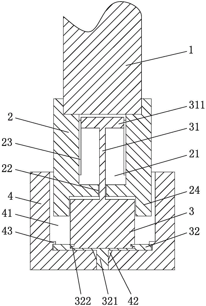
[0015] refer to figure 1 , a pressing mold for annular refractory bricks, including a punch assembly and a punch seat 4, the punch assembly includes an annular ejector pin 1, a stamping head 2, and a spacer block 3 from top to bottom, and the bottom end of the annular ejector pin 1 is The wall is provided with an external thread, and the punching head 2 is provided with a limiting groove 21, and the groove wall at the notch of the limiting groove 21 is provided with an internal thread that cooperates with the external thread, so that the punching head 2 and the annular ejector rod 1 are threaded. connect. The bottom wall of the limiting groove 21 is provided with a limiting hole 22, and the groove wall of the limiting groove 21 is provided with three axially arranged convex ribs 23, and the top surface of the spacer block 3 is provided with a rib that cooperates with the limiting hole 22. The limit rod 31, the top surface of the limit rod 31 is provided with a protrusion 311 ...


PUM


Abstract

The invention relates to a pressing mould for an annular refractory brick and belongs to the field of pressing moulds. By the adoption of the pressing mould for the annular refractory brick, the refractory brick can be conveniently taken out of a forming groove. The pressing mould for the annular refractory brick comprises a punch assembly and a punch base. The forming groove is formed in the punch base. The punch assembly comprises an annular ejector rod, a punching head and a partition block, wherein the annular ejector rod, the punching head and the partition block are arranged from top to bottom in sequence. External threads are arranged on the side wall of the bottom end of the annular ejector rod. A gap is formed between the side wall of the punching head and the wall of the forming groove. A limiting groove is formed in the punching head. The portion, at the position of a groove opening, of the wall of the limiting groove is provided with internal threads matched with the external threads. A material fetching plate is arranged on the bottom end face of the partition block. A locating block is arranged on the bottom end face of the material fetching plate. A locating hole matched with the locating block is formed in the bottom wall of the forming groove. The locating hole penetrates through the forming groove. A fixing buckle matched with the material fetching plate is arranged on the side wall of the forming groove.

Description

technical field [0001] The invention relates to a pressing die for annular refractory bricks, which belongs to the field of pressing dies. Background technique [0002] The existing refractory brick pressing die comprises a punch and a punch seat. A forming groove is arranged on the punch seat. After refractory powder is placed in the forming groove, the punch moves downward to extrude the refractory powder to form an annular refractory brick. The following two methods are usually used to take out the formed annular refractory brick from the forming groove: one is to rotate the punch seat, and after the opening of the forming groove is downward, lightly hit the side wall of the punch seat to make the annular refractory brick out of the forming groove There is a disadvantage of this method of picking parts, that is, if the punch seat is not fixed when the punch is stamped, the punch seat is easily damaged by the impact of the punch. The second is to install a push rod on the...

Claims


Application Information

Patent Timeline
Patent Type & Authority Applications(China)
IPC IPC(8): B30B15/02
Inventor 高寿林
Owner 浙江立鑫高温耐火材料有限公司
Why Eureka
Try Eureka