
An Offset Torsion Beam Elastic Tailstock

A technology of torsion beam and tailstock, applied in the field of CNC machine tool tailstock mechanism, can solve the problems of large friction coefficient of sliding friction guide rail, decreased workpiece positioning accuracy, increased workpiece vibration, etc., to achieve good rigidity, eliminate tailstock wear, reduce small vibration effect

Active Publication Date: 2017-01-25
NINGBO XIATUO MACHINERY EQUIP
View PDF7 Cites 0 Cited by
  • Summary
  • Abstract
  • Description
  • Claims
  • Application Information

AI Technical Summary

Problems solved by technology

For example, the tail tip of the metal cutting machine tool often bears the radial alternating cutting resistance in the horizontal plane, and the sleeve seat hole will produce unilateral wear under the repeated alternating cutting resistance, which will reduce the positioning accuracy of the workpiece and increase the vibration of the workpiece during processing. Large, if you want to restore the accuracy, you need to replace the top sleeve and sleeve seat by maintenance. The movement of the tailstock adopts the sliding friction guide rail. Although the positioning accuracy and rigidity can be achieved, the friction coefficient of the sliding friction guide rail is large, and the guide rail is easy to wear. Rolling linear guides will lead to insufficient rigidity, and the coaxial drive tailstock interferes with some processing operations. Only the top is lengthened and the rigidity of the tailstock is reduced. In addition, the hydraulic drive tailstock and the top sleeve are used, and the hydraulic system of the machine tool needs to work continuously. , higher energy consumption and more complicated structure

Method used


Image

  • An Offset Torsion Beam Elastic Tailstock
  • An Offset Torsion Beam Elastic Tailstock

Examples


Embodiment Construction

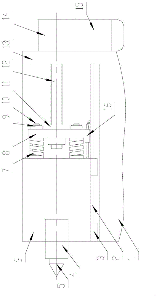
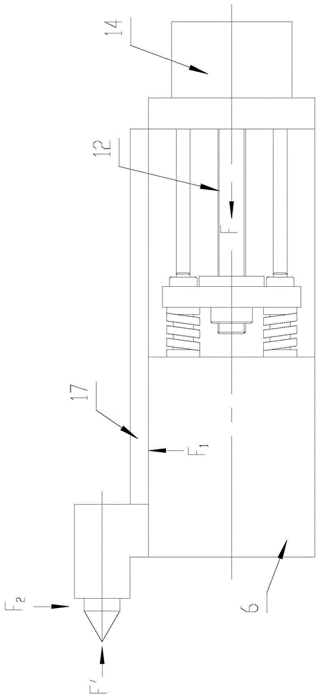
[0019] refer to Figure 1 ~ Figure 2 , the present invention provides a biased torsion beam elastic tailstock, which includes a tailstock body that is slipped on a guide rail and is equipped with a tip, and a push mechanism for pushing the tailstock body to move, wherein the axis of the tip is the same as the axis of the push mechanism The center lines of the acting force are parallel and non-axial, and an elastic component is provided between the tailstock body and the pushing mechanism; the tailstock body in this embodiment includes a box body 6 that is slidably fitted on the linear guide rail 2 through a slider 3 , preferably, the linear guide rail 2 is a rolling linear guide rail, the top is fixed on the front end of the box body 6, and four guide posts 10 are fixed on the rear end surface of the box body 6, and a push plate 8 is slid on the guide post 10, and the elastic The parts are located between the rear end face of the box body and the push plate 8, and a screw nut ...


PUM


Abstract

The invention provides an offset torsion beam elastic tailstock used for automatic clamping of a numerically-controlled machine tool. According to the offset torsion beam elastic tailstock, a tip is installed in an offset mode to form a torsion beam structure, clamping force is obtained through a compression spring, and quick advancing and retreating of the tailstock is achieved through a rolling linear guiding rail; when top clamping force is exerted on the tip, the offset torsion beam structure enables a box body of the tailstock to abut against a planar sliding friction guiding rail perpendicularly installed on the lateral side to be positioned accurately and generate pretightening force on the guiding rail; when radial action force is exerted on the tip in the horizontal direction, balance can be achieved effectively through the pretightening force, machining interference of the offset torsion beam elastic tailstock is reduced, positioning is accurate, and vibration and abrasion can be effectively reduced. The offset torsion beam elastic tailstock is suitable for a metal cutting numerically-controlled machine tool according to which a tip needs to be installed in the offset mode and the tip bears radial alternating cutting resistance which is exerted in the horizontal direction during machining.

Description

technical field [0001] The invention relates to a tailstock mechanism for a numerically controlled machine tool, in particular to a tailstock mechanism for a numerically controlled machine tool with a mechanical structure in which the tail tip is offset to form a torsion beam and which is automatically clamped. Background technique [0002] The tailstock is an essential part of a general machine tool, and its function is to locate and support the tail end of the workpiece shaft to be processed. The functions of the tailstock of the traditional CNC machine tool have been expanded on the basis of the original machine tool tailstock, including CNC drive, automatic top clamping, etc. However, the general CNC machine tool tailstock still follows the original tailstock design. The sleeve-type top tailstock is driven by hydraulic pressure and adopts sliding friction guide rails. , that is, the coaxial drive. There are deficiencies in the application of this type of tailstock on t...

Claims


Application Information

Patent Timeline
Patent Type & Authority Patents(China)
IPC IPC(8): B23B23/00
CPCB23B23/00
Inventor 刘大猷谢桂平李伟张海清
Owner NINGBO XIATUO MACHINERY EQUIP
Learn More