Spiral conveying and degreasing process

A screw conveying and process technology, which is applied in the field of screw conveying oil removal technology, can solve the problems of poor drying effect, affecting drying effect, affecting process, etc.

Active Publication Date: 2014-10-29
SHENZHEN KAIZHONG PRECISION TECH CO LTD
View PDF5 Cites 4 Cited by
  • Summary
  • Abstract
  • Description
  • Claims
  • Application Information

AI Technical Summary

Problems solved by technology

[0006] In this prior art, the drying section is arranged behind the cleaning pipe part, and is arranged inside the screw conveying drum together, and the cleaning pipe part and the drying section part are not provided with an isolation device. On the one hand, this arrangement causes the cleaning part The cleaning liquid will enter the drying section with the material, which not only affects the drying effect of the drying section, so as to affect the subsequent drying process, but also leads to the waste of cleaning liquid. On the other hand, when drying at high temperature, the liquid When it is gasified, because it cannot be discharged in time, it is easy to contact the inner wall of the spiral conveyor drum and be cooled and liquefied, which leads to poor drying effect; therefore, this method of setting the drying section inside the spiral drum is not advisable.
However, if the drying section is simply set outside the screw conveyor drum, the cleaned materials will enter the drying section from the feeding mechanism, and there is also the problem that the cleaning liquid flows into the drying section to affect the drying effect. In order to prevent the screw conveyor drum from The cleaning liquid inside enters the drying section. The traditional solution is to set a valve between the screw conveying drum and the drying section. The valve is closed when cleaning and degreasing, and the valve is opened when the cleaning and degreasing is completed. However, when the valve is opened, the cleaning The liquid will still enter the drying section with the material, which cannot completely solve the problem of poor drying effect. Therefore, simple control through the valve cannot simultaneously solve the problem of material conveying and preventing the cleaning liquid in the screw conveyor drum from flowing to the drying section. two technical questions

Method used


Image

  • Spiral conveying and degreasing process
  • Spiral conveying and degreasing process
  • Spiral conveying and degreasing process

Examples


Embodiment 1

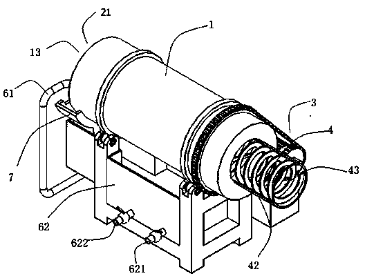
[0041] This embodiment provides a screw conveying degreasing device, such as figure 1 , 2 As shown, a screw conveyor drum 1 is included, and the screw conveyor drum 1 has an inlet and an outlet 12, and the inlet is used to input materials from the feeding mechanism into the screw conveyor drum 1, and the screw conveyor drum 1 It also includes a first spiral passage 2 arranged along its inner wall for conveying materials, and a material inlet 21 and a material outlet 22 arranged at both ends of the first spiral passage 2, and the material inlet 21 is arranged correspondingly to the inlet, so The material outlet 22 is set corresponding to the outlet 12, and the material entering the screw conveying drum 1 from the inlet enters the first spiral channel 2 from the material inlet 11; the screw conveying degreasing device It also includes a transmission mechanism 3 for driving the rotation of the screw conveyor drum 1, and the material driven by the screw conveyor drum 1 advances i...

Embodiment 2

[0055] This embodiment provides a process for degreasing using the degreasing device described in Embodiment 1, comprising the following steps:

[0056] A. The step of using the screw conveying drum 1 for screw conveying: the spiral conveying drum 1 includes a first spiral passage 2 for conveying materials arranged along its inner wall, and a material inlet 21 and a material inlet 21 arranged at both ends of the first spiral passage 2. Outlet 22, the material entering the spiral conveying drum 1 from the material inlet 21 advances in a spiral manner along the first spiral channel 2 in the spiral conveying drum 1, and finally advances to the material outlet 22;

[0057] B. The step of using degreasing agent and degreasing through degreasing assembly: using degreasing agent and degreasing the material through degreasing assembly 6 during the spiral advance of the material; The above-mentioned material outlet 22 enters the revolving conveying assembly 4, and is conveyed by the r...


PUM


Abstract

The invention provides a spiral conveying and degreasing process. In the spiral conveying step, a circulation conveying assembly is arranged and comprises a bucket and a circulation roller, wherein the bucket is fixedly arranged on the inner wall of a spiral conveying roller and provided with a bucket opening; the bucket opening is opposite to a first spiral outlet of a first spiral channel, and a cleaning fluid filtering port is formed in the bucket; one end of the circulation roller penetrates through a spiral conveying outlet of the spiral conveying roller and is located in the spiral conveying roller, and the other end of the circulation roller is connected with a material receiving mechanism in the next process; the end, located in the spiral conveying roller, of the circulation roller is closed, and a receiving port corresponding to the bucket opening is formed in the sidewall, close to the closed end, of the circulation roller and used for receiving materials dumped by the bucket. By the adoption of the spiral conveying and degreasing process, the process that a degreasing portion conveys the materials to a drying section for drying is not affected, and degreasing agents of the degreasing portion can also be prevented from entering the drying section.

Description

technical field [0001] The invention relates to a screw conveying degreasing process, in particular to a process for cleaning and degreasing materials by using a spiral material conveying device. Background technique [0002] With the development of society and the progress of the times, people have higher and higher requirements for the quality of ring mirrors, so environmental protection has become a common concern in today's society. The recycling of industrial waste can not only reduce environmental pollution, but also save energy and play a positive role in driving social benefits. [0003] The recycling and reuse of industrial waste first requires decontamination and cleaning of industrial waste. Taking the recycling and reuse of scrap copper as an example, the oil stain attached to scrap copper should be removed first. The traditional method of degreasing copper scrap is manual removal. Oil pollution, like this, not only wastes time, increases labor intensity, and de...

Claims


Application Information

Patent Timeline
IPC IPC(8): B08B3/02B08B13/00B65G33/26
CPCB08B3/022B65G33/265
Inventor 张浩宇
Owner SHENZHEN KAIZHONG PRECISION TECH CO LTD
Why Eureka
Try Eureka