A High Gain Low Noise Differential Transimpedance Amplifier

A transimpedance amplifier and low-noise technology, applied in the field of high-gain, low-noise differential transimpedance amplifiers, can solve problems such as small bandwidth, high noise, and insufficient gain, and achieve fewer tubes, reduced power consumption, and reduced chip area Effect

Active Publication Date: 2017-07-04
XIDIAN UNIV
View PDF4 Cites 0 Cited by
  • Summary
  • Abstract
  • Description
  • Claims
  • Application Information

AI Technical Summary

Problems solved by technology

Low-impedance amplifiers have simple structure and large bandwidth, but the gain is not high enough, and the noise is large, while high-impedance amplifiers have high sensitivity and low noise, but have the disadvantages of small bandwidth and narrow dynamic range. Choosing a transimpedance amplifier can meet these performance requirements good compromise

Method used


Image

  • A High Gain Low Noise Differential Transimpedance Amplifier
  • A High Gain Low Noise Differential Transimpedance Amplifier
  • A High Gain Low Noise Differential Transimpedance Amplifier

Examples


Embodiment Construction

[0044] In order to make the technical problems, technical solutions and advantages to be solved by the present invention clearer, the following will describe in detail with reference to the drawings and specific embodiments.

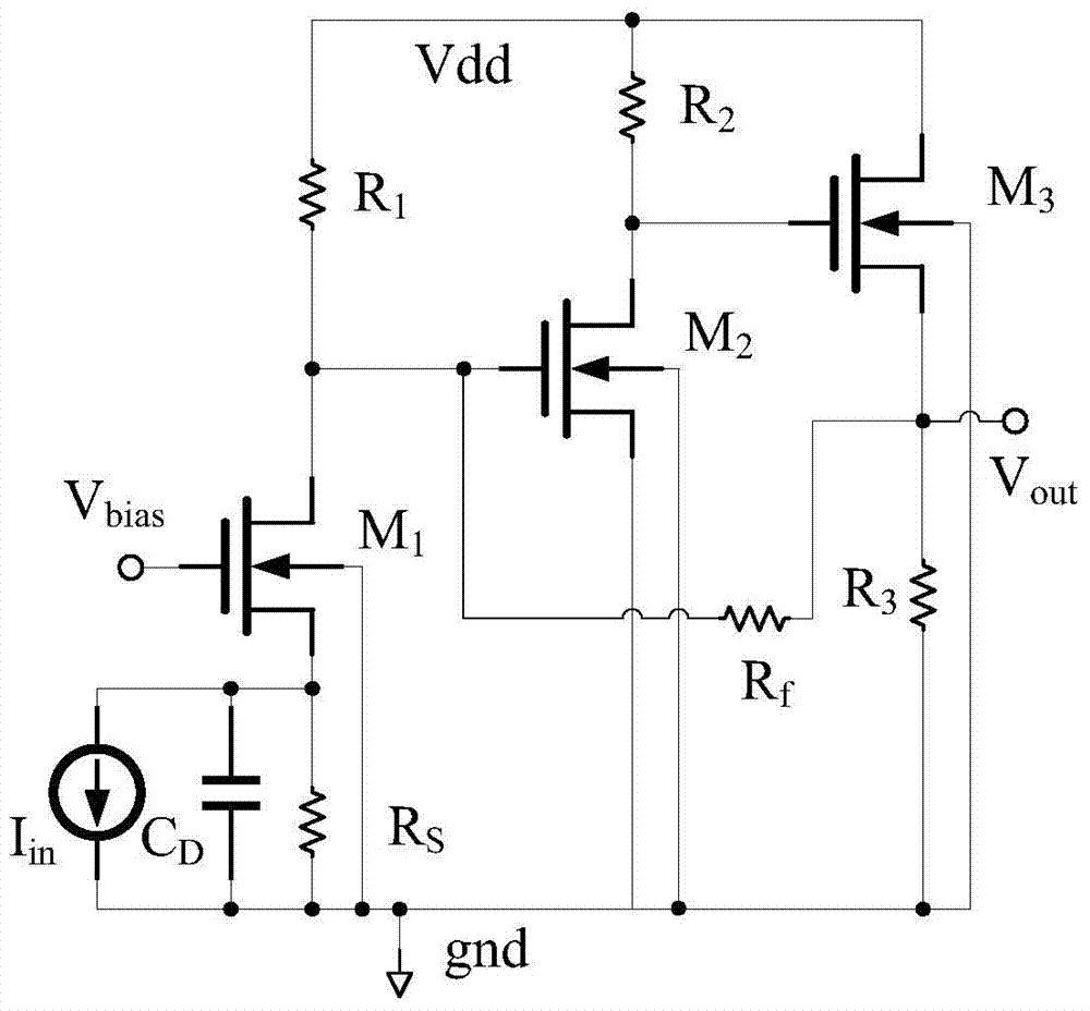
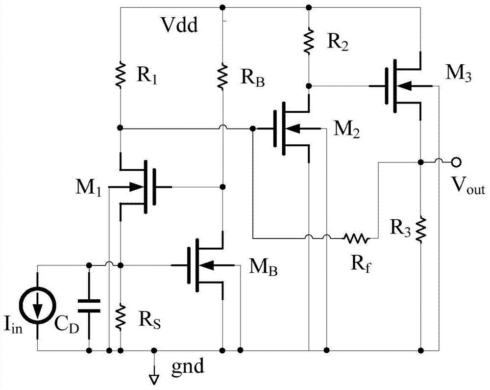
[0045] Such as figure 2 Shown is the circuit diagram of the RGC (Regulated-Cascade, adjusted cascode) transimpedance amplifier.

[0046] exist figure 2 Among them, Vdd is the power supply voltage, gnd is the ground terminal, I in is the input current signal, C D is the photodetector parasitic capacitance, V out is the output voltage signal;

[0047] and figure 1 Compared with the current-mode form transimpedance amplifier structure shown, figure 2 The RGC transimpedance amplifier shown adds the NMOS transistor M B and resistor R B A common source amplifier is used as a negative feedback path, and the NMOS transistor M 1 Provide bias voltage; if M 1 The drain-source current increases, the resistor R S The voltage drop increases, that is, the...


PUM


Abstract

The invention provides a high-gain and low-noise differential trans-impedance amplifier. The high-gain and low-noise differential trans-impedance amplifier comprises a current mirror, an adjusting type common-emitter and common-base trans-impedance amplifier and an output common-source amplifier, wherein the adjusting type common-emitter and common-base tarns-impedance amplifier comprises a common-base amplifying unit and a negative feedback common-emitter amplifying unit; the negative feedback common-emitter amplifying unit is arranged between an emitter and a base of the common-base amplifying unit and serves as a negative feedback channel; input current is copied by the current mirror in an equal proportion manner; the current mirror provides bias voltage for the common-base amplifying unit and the negative feedback common-emitter amplifying unit; the output common-source amplifier is connected between an output end of the adjusting type common-emitter and common-base trans-impedance amplifier and an output end of the high-gain and low-noise differential trans-impedance amplifier; and trans-impedance gain is increased. By the high-gain and low-noise differential tarns-impedance amplifier, received weak signals are amplified in a high-gain and low-noise manner, bandwidth is large, and a dynamic range of inputted current signals are reasonably set; and the high-gain and low-noise differential tarns-impedance amplifier has the advantages of easiness in design and monolithic integration.

Description

technical field [0001] The invention relates to the field of integrated circuits, in particular to a high-gain, low-noise differential transimpedance amplifier. Background technique [0002] In fiber optic communication systems, preamplifiers have a significant impact on the performance of the entire system, such as speed, sensitivity, and signal-to-noise ratio. According to the characteristics of the bias resistor, there are three optional preamplifiers: low impedance amplifier, transimpedance amplifier and high impedance amplifier. Low-impedance amplifiers have simple structure and large bandwidth, but the gain is not high enough, and the noise is large, while high-impedance amplifiers have high sensitivity and low noise, but have the disadvantages of small bandwidth and narrow dynamic range. Choosing a transimpedance amplifier can meet these performance requirements A good compromise was achieved. [0003] Such as figure 1 Shown is the structure diagram of the current-...

Claims


Application Information

Patent Timeline
Patent Type & Authority Patents(China)
IPC IPC(8): H03F3/45
Inventor 刘帘曦马丽邹姣朱樟明杨银堂
Owner XIDIAN UNIV
Why Eureka
Try Eureka