
Intelligent power module

A technology of intelligent power modules and bridge arms, which is applied in the direction of output power conversion devices and electrical components, and can solve the problems of reducing the manufacturing cost of intelligent power modules, large circuit noise, and burning of intelligent power modules

Active Publication Date: 2014-10-22
GD MIDEA AIR-CONDITIONING EQUIP CO LTD
View PDF6 Cites 11 Cited by
  • Summary
  • Abstract
  • Description
  • Claims
  • Application Information

AI Technical Summary

Problems solved by technology

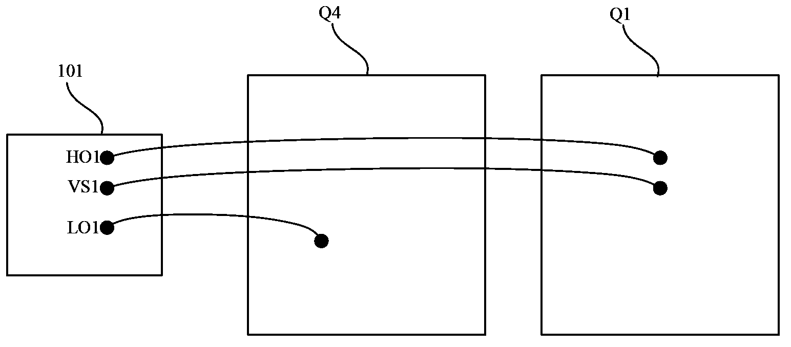
[0014] The purpose of the present invention is to provide an intelligent power module, aiming at solving the low switching efficiency and circuit noise of the IGBT tube due to the excessively long jumper wire between the HVIC chip and the gate of the IGBT tube in the existing intelligent power module Large, and when the IGBT tubes of the upper and lower bridge arms are turned on at the same time, the intelligent power module will be burned due to overcurrent, and at the same time reduce the manufacturing cost of the intelligent power module

Method used


Image

  • Intelligent power module
  • Intelligent power module
  • Intelligent power module

Examples


Embodiment Construction

[0049] In order to make the object, technical solution and advantages of the present invention clearer, the present invention will be further described in detail below in conjunction with the accompanying drawings and embodiments. It should be understood that the specific embodiments described here are only used to explain the present invention, not to limit the present invention.

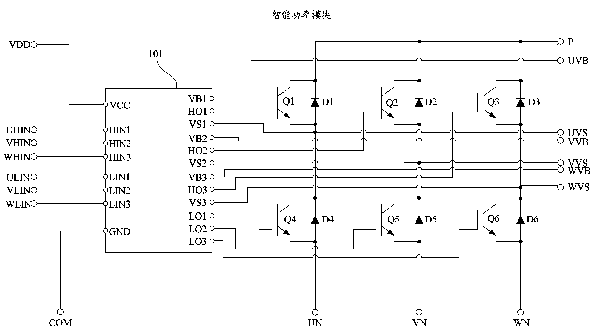
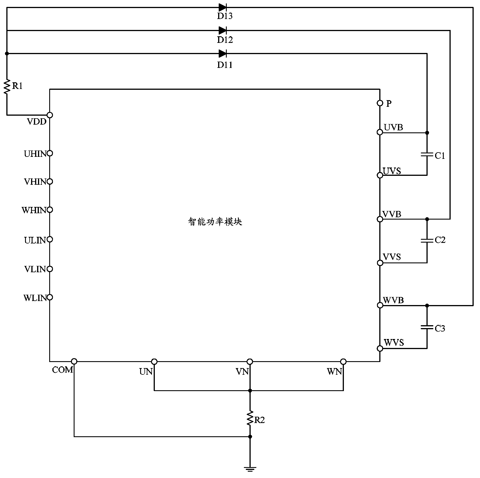
[0050] In the embodiment of the present invention, the input circuit, the U-phase upper bridge arm output circuit, the V-phase upper bridge arm output circuit, the W-phase upper bridge arm output circuit, the U-phase lower bridge arm output circuit, and the V-phase lower bridge arm output circuit are used in the intelligent power module. arm output circuit and W-phase lower bridge arm output circuit, so that each IGBT tube is driven by an independent circuit, which effectively shortens the jumper between the circuit and the gate of the IGBT tube, reduces the gate inductance, and reduces The circuit...


PUM


Abstract

The invention belongs to the field of power drive control, and provides an intelligent power module. An input circuit, a U-phase upper bridge arm output circuit, a V-phase upper bridge arm output circuit, a W-phase upper bridge arm output circuit, a U-phase lower bridge arm output circuit, a V-phase lower bridge arm output circuit and a W-phase lower bridge arm output circuit are adopted in the intelligent power module so that each IGBT tube is driven by an independent circuit, a jumper wire between the circuit and the gate electrode of the IGBT tube is effectively reduced, gate electrode inductance is reduced, circuit noise is reduced, and thus switching speed of the IGBT tubes is enhanced. Besides, switching time of the IGBT tubes of upper and lower bridge arms are maintained to be consistent without conduction at the same time so that safety of the intelligent power module is enhanced. Furthermore, the U-phase lower bridge arm output circuit, the V-phase lower bridge arm output circuit and the W-phase lower bridge arm output circuit are low-voltage area circuits so that technical manufacturing cost is relatively low, and thus manufacturing cost of the overall intelligent power module can be substantially reduced.

Description

technical field [0001] The invention belongs to the field of power drive control, in particular to an intelligent power module. Background technique [0002] Intelligent Power Module (IPM, Intelligent Power Module) is a power drive product that combines power electronics technology and integrated circuit technology. The intelligent power module integrates the power switching device and the high-voltage driving circuit, and has built-in fault detection circuits such as overvoltage, overcurrent and overheating. On the one hand, the intelligent power module receives the control signal from the MCU and drives the subsequent circuit to work; on the other hand, it feeds back the system status detection signal to the MCU. Compared with traditional discrete solutions, intelligent power modules have won an increasing market due to their advantages of high integration and high reliability. They are especially suitable for inverters and various inverter power supplies for driving moto...

Claims


Application Information

Patent Timeline
IPC IPC(8): H02M1/088
Inventor 冯宇翔
Owner GD MIDEA AIR-CONDITIONING EQUIP CO LTD
Learn More