
Electro-optic phase modulator with low additional strength

An electro-optical phase modulation and additional intensity technology, which is applied in the direction of instruments, optics, nonlinear optics, etc., can solve the problems of inaccurate interference light intensity measurement, interference of interference light intensity measurement, affecting the accuracy of electro-optic phase modulation, etc., and achieve electric field mutation Smooth rate, improved modulation accuracy, and improved accuracy

Active Publication Date: 2014-10-22
THE 44TH INST OF CHINA ELECTRONICS TECH GROUP CORP
View PDF5 Cites 0 Cited by
  • Summary
  • Abstract
  • Description
  • Claims
  • Application Information

AI Technical Summary

Problems solved by technology

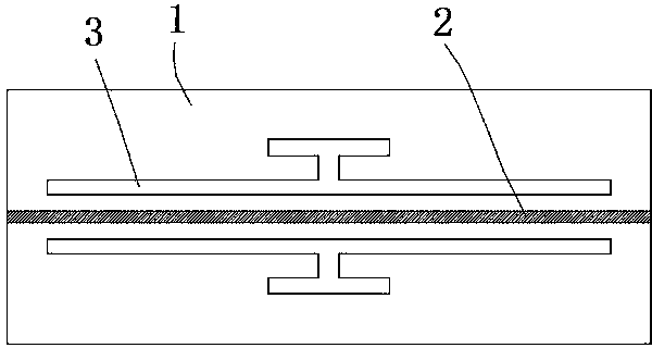
[0004] The problems existing in the aforementioned prior art are: based on the existing design idea, the two electrodes in the electro-optical phase modulator are straight strips, the gap width between the two electrodes is uniform, and the electric field strength within the gap capacitance range It is also uniform, which leads to a large electric field mutation rate between the inside and outside of the gap capacitance. Correspondingly, there is also a large refractive index mutation rate between the modulated section and the unmodulated section on the optical waveguide. In addition, the electric field mutation rate There is a correlation between the rate and the strength of the electric field modulation. The stronger the electric field modulation, the greater the electric field mutation rate, and the corresponding refractive index mutation rate is also larger; when the optical signal is transmitted to the junction of the modulated section and the unmodulated section , due to a sudden change in the refractive index, the optical signal will be partially reflected. The amount of reflection has an impact on the light intensity, and there is a correlation between the amount of reflection and the abrupt change rate of the refractive index. When the strength of the electric field modulation changes, the amount of reflection The size also changes dynamically, which will interfere with the measurement of the interference light intensity, resulting in inaccurate measurement of the interference light intensity, which will eventually affect the accuracy of the electro-optical phase modulation

Method used


Image

  • Electro-optic phase modulator with low additional strength
  • Electro-optic phase modulator with low additional strength
  • Electro-optic phase modulator with low additional strength

Examples


Embodiment Construction

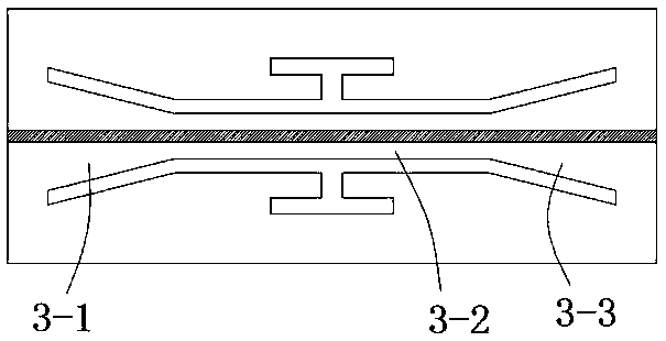
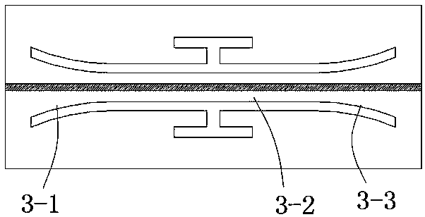
[0020] An electro-optic phase modulator with low additional strength, comprising a chip 1, an optical waveguide 2 and two electrodes 3, the electrodes 3 are arranged on the chip 1, a gap is left between the two electrodes 3, and between the two electrodes 3 The gap between the gaps forms a gap capacitor, the optical waveguide 2 is arranged in the gap capacitor on the chip 1, and the axial direction of the optical waveguide 2 is parallel to the axial direction of the gap capacitor; sections, wherein the right end of the first section 3-1 is connected to the left end of the second section 3-2, and the right end of the second section 3-2 is connected to the left end of the third section 3-3; the first Within the scope of section 3-1, the width of the gap between the two electrodes 3 gradually narrows from left to right; within the scope of the second section 3-2, the width of the gap between the two electrodes 3 is uniform; the third section 3-3, the gap width between the two ele...


PUM


Abstract

The invention relates to an electro-optic phase modulator with low additional strength. The electro-optic phase modulator comprises a chip, an optical waveguide and two electrodes. The electro-optic phase modulator is characterized in that three sections are respectively formed on a gap capacitor in an axial direction, wherein the right end of the first section is connected with the left end of the second section, and the right end of the second section is connected with the left end of the third section; the gap width within the range of the first section and between the two electrodes is gradually narrowed from left to right; the gap width within the range of the second section and between the two electrodes is uniform; the gap width within the range of the third section and between the two electrodes is gradually widened from left to right; the gap width of the right end of the first section is the same as the gap width of the second section, and the gap width of the left end of the third section is the same as the gap width of the second section. According to the electro-optic phase modulator, the mutation rate of an electric field positioned between the inside and external environment of the gap capacitor is gentler, so that the variation range of output light intensity is reduced, and the modulating accuracy of the electro-optic phase modulator is improved by enhancing the measurement accuracy of interference light intensity.

Description

technical field [0001] The invention relates to an electro-optic phase modulator, in particular to an electro-optic phase modulator with low additional strength. Background technique [0002] Electro-optic phase modulators have important application value in the fields of laser technology, optical communication, optical sensing and optical testing, and their typical applications are fiber optic current sensors, fiber optic gyroscopes, etc. The basic principle of the electro-optical phase modulator is to form an optical waveguide on a substrate such as lithium niobate through proton exchange or diffusion, and change the refractive index of the optical waveguide by applying a directional electric field to the optical waveguide. The change of the refractive index will cause the light in the optical waveguide to The phase of the signal changes, so we can adjust the phase of the optical signal by adjusting the refractive index of the optical waveguide. [0003] In the prior ...

Claims


Application Information

Patent Timeline
Patent Type & Authority Applications(China)
IPC IPC(8): G02F1/035
Inventor 华勇张洪波胡红坤杨相川刘韵
Owner THE 44TH INST OF CHINA ELECTRONICS TECH GROUP CORP
Learn More