
Evaporation source device for evaporator and evaporator

A technology of evaporation machine and evaporation source, which is applied in vacuum evaporation coating, sputtering coating, ion implantation coating and other directions, can solve the problem of reducing the yield of evaporation material, uneven heat transfer, poor thermal conductivity, etc. The problem is to reduce the low thermal conductivity, improve the uniformity of heat transfer, and shorten the heat transfer path.

Active Publication Date: 2014-10-22
HEFEI XINSHENG OPTOELECTRONICS TECH CO LTD +1
View PDF4 Cites 9 Cited by
  • Summary
  • Abstract
  • Description
  • Claims
  • Application Information

AI Technical Summary

Problems solved by technology

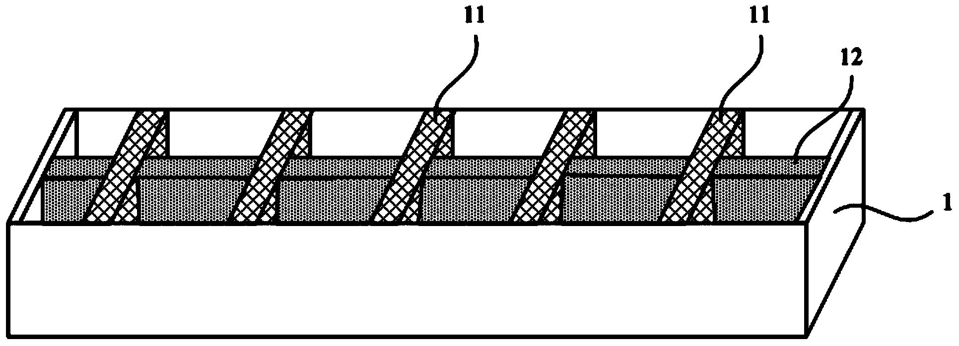
[0003] like figure 1 As shown, the evaporation source device of the existing OLED vapor deposition machine includes a crucible 1 containing organic materials, and the crucible 1 is heated to realize the evaporation of the organic materials in the crucible 1. Since the heating of the crucible 1 is only the 1 around the crucible wall for heating, the structure of the crucible 1 is generally figure 1 The long strip shape shown, therefore, for the organic material in the crucible groove of the crucible 1, the thermal conductivity of the organic material itself is poor, and the heat conduction path is long, which is easy to cause uneven heat transfer, especially for large-scale evaporation As far as the source is concerned, the phenomenon of uneven temperature distribution is more obvious, which in turn causes problems such as insufficient stability of the deposition rate of the evaporation of organic materials and a decrease in yield.
[0004] The crucible of the existing evaporation source is easy to cause uneven heat transfer of the evaporation material, thereby reducing the yield of the evaporation material evaporation

Method used


Image

  • Evaporation source device for evaporator and evaporator
  • Evaporation source device for evaporator and evaporator
  • Evaporation source device for evaporator and evaporator

Examples


Embodiment Construction

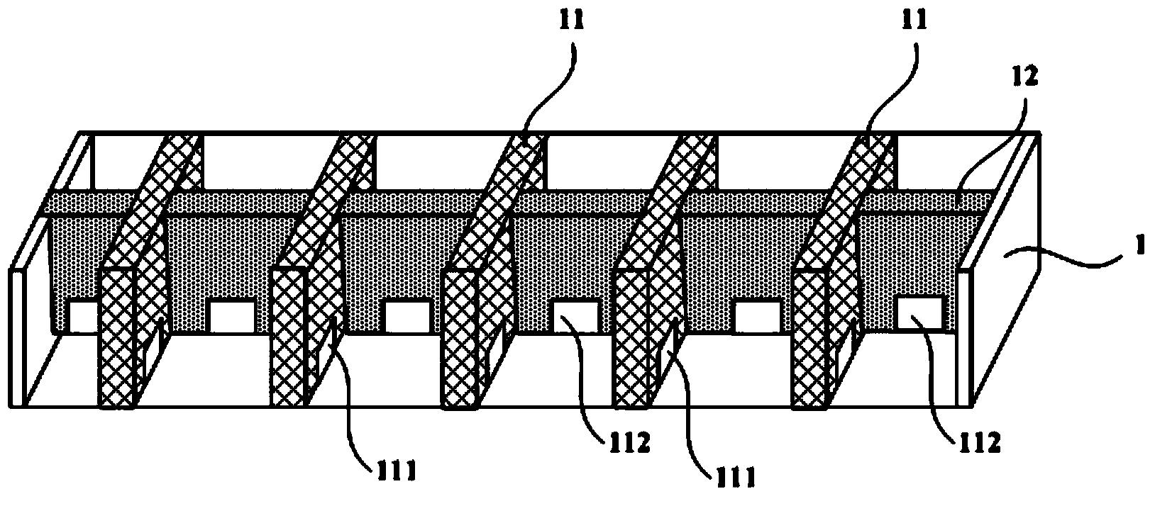
[0028] In order to improve the heat transfer uniformity of the vapor deposition material, an embodiment of the present invention provides an evaporation source device of the vapor deposition machine and an vapor deposition machine. In this technical solution, since a plurality of first thermally conductive partitions along the first direction and a plurality of second thermally conductive partitions along the second direction are used in the crucible groove, the first thermally conductive partitions and the second thermally conductive partitions can separate the crucible The heat of the wall is conducted, therefore, the vapor deposition materials in the multiple storage tanks composed of the first heat conduction partition and the second heat conduction partition are heated evenly, which greatly reduces the influence of the vapor deposition material from its own low thermal conductivity , Therefore, the uniformity of heat transfer can be greatly improved, thereby improving the ...


PUM


Abstract

The invention relates to the technical field of evaporation equipment, and discloses an evaporation source device for an evaporator and the evaporator. The evaporation source device for evaporator provided by the invention comprises a crucible; the crucible slot of the crucible is provided with at least one first conductive clapboard along a first direction, and each of the first conductive clapboard is connected with the crucible wall; and the crucible slot is provided with at least one second conductive clapboard fixedly connected with the first conductive clapboard along a second direction, and each of the second conductive clapboard is connected with the crucible wall. The technical scheme provided by the invention can shorten the heat transfer path in an evaporation material, realize even transfer of heat in the evaporation material, and further improve the thermal stability of the organic material evaporation, thereby maintaining stability of plating rate and improving the yield rate of the organic material evaporation.

Description

technical field [0001] The invention relates to the technical field of evaporation equipment, in particular to an evaporation source device of an evaporation machine and an evaporation machine. Background technique [0002] Organic Light-Emitting Diode (OLED for short) manufactures a carrier transport layer and an organic light-emitting layer constituting an OLED display device by evaporating organic materials. The evaporation sources of today's OLED evaporation machines are divided into point source evaporation sources and linear evaporation sources. Since linear evaporation sources can improve the utilization rate of evaporation materials and the uniformity of film formation, linear evaporation sources are regarded as a research hotspot. There is widespread concern. The organic evaporation materials evaporated in the evaporation source device are mainly divided into two types, one is sublimation organic materials, and the other is melting organic materials. Among them, t...

Claims


Application Information

Patent Timeline
IPC IPC(8): C23C14/24C23C14/12
Inventor 叶岚凯黄俊淞
Owner HEFEI XINSHENG OPTOELECTRONICS TECH CO LTD
Learn More