A fully mixed internal circulation suspended packing biological denitrification reactor

A technology for suspended filler and biological denitrification, which is applied to the field of internal circulating suspended filler biological denitrification reactors, can solve the problems of ineffective treatment, affect the efficiency of wastewater treatment, adversely affect the effect of wastewater treatment, and improve the efficiency of wastewater treatment. , Strengthen the effect of wastewater treatment, shorten the effect of the film hanging time of the filler

Active Publication Date: 2016-01-27
SICHUAN UNIV
View PDF1 Cites 0 Cited by
  • Summary
  • Abstract
  • Description
  • Claims
  • Application Information

AI Technical Summary

Problems solved by technology

The structure of the existing moving bed biofilm reactor is a square tank body. The single tank body is relatively large. The biological filler is trapped in the pool body, and fillers are placed in the pool body. The moving bed biofilm reactor with this structure has the following disadvantages in the treatment of wastewater: (1) When treating wastewater, the wastewater circulates in the pool body under the action of aeration However, due to the square shape of the pool body and the large volume of the pool, there is a large area of ​​dead space in the pool body, especially the upper and lower corners of the pool body. The waste water in the lower corner of the pool body moves very slowly, and the pollutants in the waste water If it is deposited here, it cannot be effectively treated, which affects the efficiency of wastewater treatment; (2) When the biofilm is cultivated at the initial stage of the reactor, the filler will float on the surface of the water body, and as the biofilm grows, the filler will gradually suspend in the water body However, since the wastewater in the upper corner of the pool hardly moves, the filler will float and gather in the upper corner of the pool, resulting in too long a time for the filler biofilm to be cultivated. Generally, it takes about three to four weeks to complete the filler. (3) Screens or tumbler cages are used to retain biological fillers on the outlet side, and the fillers are easy to accumulate on the inner wall of the screens or tumblers. The accumulation of fillers will cause partial blockage of the reactor and affect the water outlet. When the blockage is serious, it will cause The screen or the cage is squeezed and deformed, which eventually causes the filler to flow out of the reactor, which adversely affects the wastewater treatment effect

Method used


Image

  • A fully mixed internal circulation suspended packing biological denitrification reactor
  • A fully mixed internal circulation suspended packing biological denitrification reactor
  • A fully mixed internal circulation suspended packing biological denitrification reactor

Examples


Embodiment 1

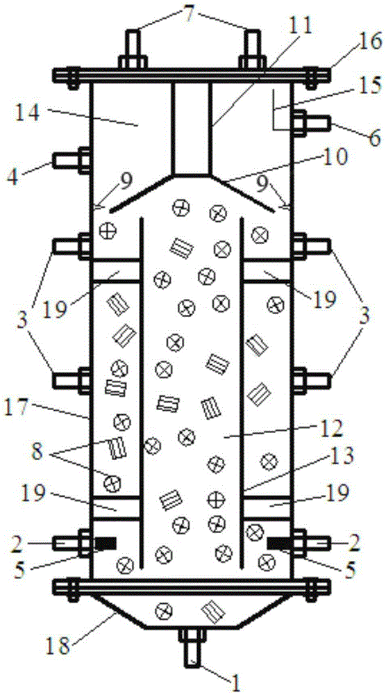
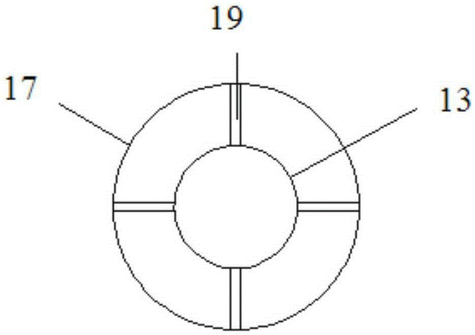
[0024] In this example, the structural schematic diagram of the biological denitrification reactor with fully mixed internal circulation suspended packing is shown in figure 1 , the reactor comprises a reactor main body, a suspension packing 8, a separation cover 10, a separation ring 9 and an inner sleeve 13; The lower cover 18 at the bottom of the cylindrical shell is composed of the height of the cylindrical shell 17 and the ratio of its inner diameter is 5:1; the separation cover 10 is a conical cover with a small top and a large bottom, and the opening is downward. The upper end of the separation cover 10 passes through the first A connecting rod 11 is connected with the upper cover 16, and the gap between the periphery of the lower end of the separation cover and the separation ring 9 arranged on the inner wall of the cylindrical shell is the water outlet seam, and the width of the water outlet seam is 15 mm. The chamber is divided into an upper settling area 14 and a lo...

Embodiment 2

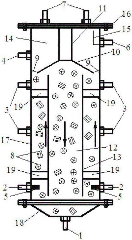
[0028] In this example, the structural schematic diagram of the biological denitrification reactor with fully mixed internal circulation suspended packing is shown in Figure 4, the reactor comprises a reactor main body, a suspension packing 8, a separation cover 10, a separation ring 9 and an inner sleeve 13; The lower cover 18 at the bottom of the cylindrical shell is composed of the height of the cylindrical shell 17 and the ratio of its inner diameter to 2:1; the separation cover 10 is a conical cover with a small top and a large bottom, and the opening is downward. The upper end of the separation cover 10 passes through the first A connecting rod 11 is connected with the upper cover 16, and the gap between the periphery of the lower end of the separation cover and the separation ring 9 arranged on the inner wall of the cylindrical shell is the water outlet seam, and the width of the water outlet seam is 20 mm. The chamber is divided into an upper settling area 14 and a lo...


PUM

PropertyMeasurementUnit
densityaaaaaaaaaa

Abstract

The invention relates to a full-hybrid internal-circulating suspended filler biological denitrification reactor which comprises a reactor main body, a suspended filler, a separation cover, a separation ring and an inner sleeve, wherein the reactor main body comprises a cylinder shell, an upper cover and a lower cover; the upper cover and the lower cover are arranged at the top and bottom of the cylinder shell respectively; the upper end of the separation cover is connected with the upper cover through a first connecting rod, and a gap between the periphery of the lower end of the separation cover and the separation ring arranged on the inner wall of the cylinder shell is a water outflow seam; the separation cover divides the inner cavity of the cylinder shell into an upper sedimentation area and a lower biological reaction area; the inner sleeve is a cylinder and is arranged in the biological reaction area; the suspended filler fills in the biological reaction area; the lower part of the cylinder shell or the lower cover is provided with an air inlet and a water inlet which are communicated with the biological reaction area, the air inlet is in connect with an aeration head positioned in the biological reaction area, and the upper part of the cylinder shell is provided with a reflux water outlet and a treated water outlet which are communicated with the sedimentation area; the upper cover is provided with an air outlet communicated with the sedimentation area.

Description

technical field [0001] The invention belongs to the technical field of wastewater biological treatment, and in particular relates to a biological denitrification reactor for internal circulation suspended fillers. Background technique [0002] Wastewater treatment methods are mainly divided into physical and chemical treatment and biological treatment. Biological treatment technology is most widely used in wastewater treatment because of its low treatment cost and stable operation effect. Biological treatment technology mainly relies on the metabolism of microorganisms to remove pollutants contained in wastewater, and the corresponding biological treatment processes mainly include activated sludge method and biofilm method. Suspended packing bioreactor, also known as moving bed biofilm reactor (MBBR), is used in wastewater biological treatment process mainly based on biofilm method. The structure of the existing moving bed biofilm reactor is a square tank body. The single t...

Claims


Application Information

Patent Timeline
Patent Type & Authority Patents(China)
IPC IPC(8): C02F3/08
CPCY02W10/10
Inventor 李慧强刘兴鹏杨平陈婷婷
Owner SICHUAN UNIV
Why Eureka
Try Eureka