
string length grinder

A mill and frame technology, which is applied in the field of chord mills, can solve problems such as shape and position tolerances of tile-shaped magnets, and achieve the effects of reduced volume, good economy, and reduced length

Active Publication Date: 2016-08-24
德昌电机(南京)有限公司
View PDF5 Cites 0 Cited by
  • Summary
  • Abstract
  • Description
  • Claims
  • Application Information

AI Technical Summary

Problems solved by technology

[0003] The purpose of the present invention is to provide a chord length grinding machine to solve the technical defects of the prior art in the process of grinding tile-shaped magnets.

Method used


Image

  • string length grinder
  • string length grinder
  • string length grinder

Examples


Embodiment Construction

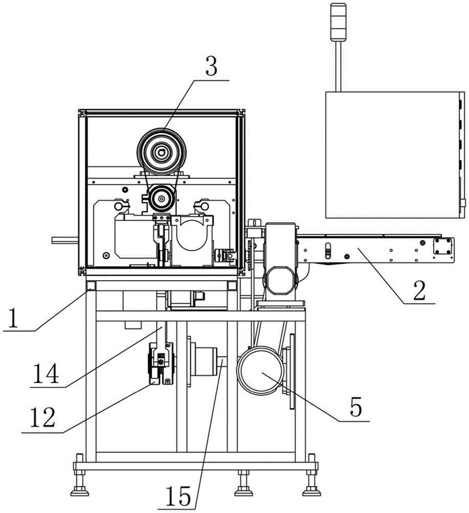
[0043] The specific embodiments of the present invention will be further described below in conjunction with the accompanying drawings.

[0044] In the present invention, the conveying direction of the tile-shaped magnet on the guide rail is the front, and the direction opposite to the tile-shaped magnet conveying direction is the back. Looking forward from the back, the direction on the left-hand side is left, and the direction on the right-hand side is right.

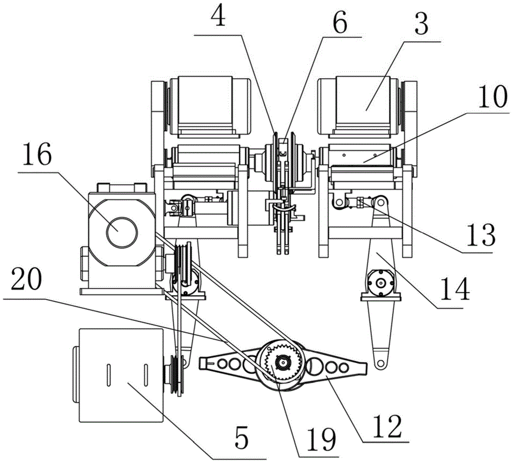
[0045] Such as Figure 1 to Figure 9 The string length mill shown includes the following components:

[0046] ① Rack 1 and bracket 1 are used to support all other components.

[0047] ② The guide rail 2 arranged horizontally on the upper part of the rack 1 .

[0048] ③ Two grinding wheels 4 are symmetrically arranged on both sides of the guide rail 2 and driven by the first motor 3. The center line of the two grinding wheels 4 is parallel to the horizontal plane and perpendicular to the guide rail 2. The two grindin...


PUM


Abstract

The invention discloses a chord grinding machine. The chord grinding machine comprises a machine frame, a guide rail, two grinding wheels, a drive mechanism and a chuck, wherein the two grinding wheels are driven by a first motor, the drive mechanism is used for driving the two grinding wheels to horizontally move, the chuck is arranged on the machine frame through a rotary shaft and is driven by a servo motor to rotate, an annular groove is formed in the outer circumferential surface of the chuck, one or more working grooves penetrating through the two bottom faces of the chuck are formed in the edge of the chuck in the axial direction, the depth of the working grooves is smaller than that of the annular groove, the chuck is arranged between the two grinding wheels and is parallel with the two grinding wheels, the position where each grinding wheel is located on the machine frame is higher than the position where the chuck is located on the machine frame, the height of the bottommost end of each grinding wheel is smaller than that of the topmost end of the chuck, the guide rail is composed of a front guide rail section and a rear guide rail section, and the chuck is located between the front guide rail section and the rear guide rail section. The chord grinding machine has the advantages that in the process that the grinding wheels grind tile-shaped magnets, the positions of the tile-shaped magnets are fixed relatively, and the tile-shaped magnets will not twist in the grinding process, so that form and location tolerance is avoided.

Description

technical field [0001] The invention belongs to the field of magnetic material manufacture, and relates to a string length grinder. Background technique [0002] Tile-shaped magnets are permanent magnets commonly used in permanent magnet motors. The manufacturing and grinding of tile-shaped magnets in the material industry generally undergoes chamfer grinding, chord length grinding, external cylindrical grinding, internal cylindrical grinding and shaft height grinding. The process is processed on different machines respectively. Among them, the chord length grinding machine is two guide rails, and a grinding wheel driven by a motor is installed on both sides of the guide rail. The motor drives the grinding wheel to rotate, and the magnet passing between the grinding wheels Grinding, in the prior art, the tile-shaped magnets are transported on the track and the grinding process is always in a moving state. In the process of grinding the tile-shaped magnets in this way of cutt...

Claims


Application Information

Patent Timeline
Patent Type & Authority Patents(China)
IPC IPC(8): B24B7/17B24B41/06B24B41/04B24B47/00
CPCB24B7/17B24B41/005B24B41/04B24B41/06B24B47/00
Inventor 薛定生祝贵鹏
Owner 德昌电机(南京)有限公司
Learn More