A Cooling System for Electric Spindle Core

A technology of cooling system and motorized spindle, applied in metal processing machinery parts, maintenance and safety accessories, metal processing equipment, etc., can solve the problem of heat dissipation of motorized spindle, stability and reliability problems, heat exchange power of heat pipe, etc. that cannot be effectively solved. limited and other problems, to achieve the effect of efficient and reliable cooling structure, low design and development cost, simple and efficient system equipment

Inactive Publication Date: 2016-08-03
XI AN JIAOTONG UNIV
View PDF5 Cites 0 Cited by
  • Summary
  • Abstract
  • Description
  • Claims
  • Application Information

AI Technical Summary

Problems solved by technology

However, the above-mentioned cooling technology has the following deficiencies in practical application: for the solution (1), although the problem of poor heat dissipation of the built-in motor has been improved, the axial dimension of the entire spindle unit is increased due to the rear placement of the motor, and the output of the electric spindle unit Reduced, thus limiting the application of electric spindles with this structure (it is only suitable for small high-speed CNC machine tools)
For solution (2), the heat pipe technology is applied to the cooling of the electric spindle. Although it can cool the electric spindle core to a certain extent, the condensation section of the heat pipe cannot be directly cooled by liquid cooling medium, but by cooling air. Heat exchange; coupled with the limited heat exchange power of the heat pipe, this cooling solution cannot effectively solve the heat dissipation problem caused by the long-term and high-power machining of the electric spindle
In addition, there are problems with the stability and reliability of its operation

Method used


Image

  • A Cooling System for Electric Spindle Core
  • A Cooling System for Electric Spindle Core
  • A Cooling System for Electric Spindle Core

Examples


Embodiment Construction

[0024] Below in conjunction with accompanying drawing, the present invention is described in further detail:

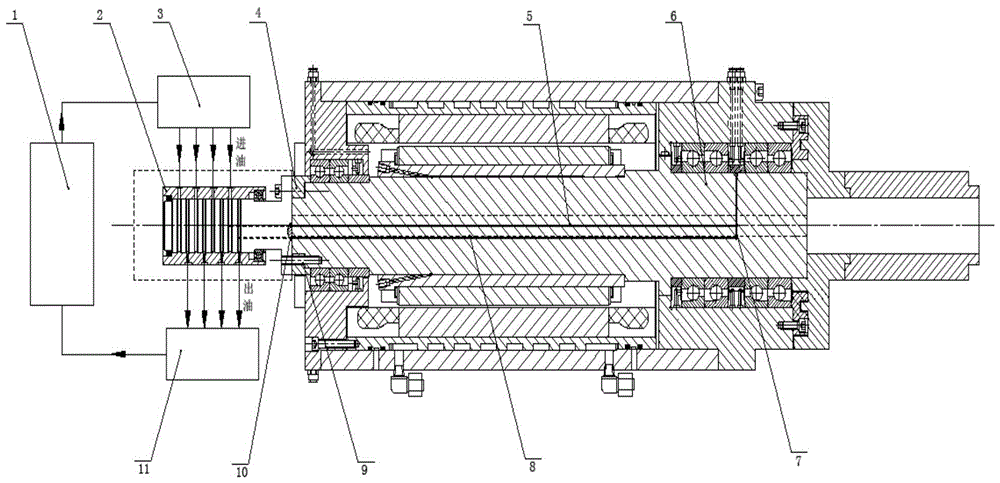
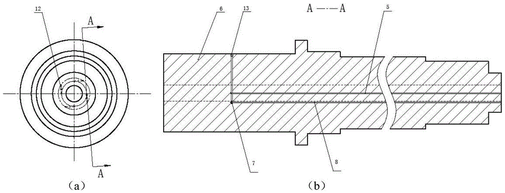
[0025] Reference attached figure 1 and 2 , an electric spindle core cooling system of the present invention, a plurality of U-shaped cooling units 12 composed of straight-hole micro-channels are processed on the electric-spindle core 6, and the diameter of the straight-hole micro-channels is less than or equal to 3mm. A single U-shaped cooling unit 12 is composed of an inflow channel 5 , a return flow channel 8 and a connecting channel 7 located at the shaft core of the electric spindle near the front bearing. The processing position of the connecting channel 7 of a single U-shaped cooling unit 12 should avoid the interference fit between the inner ring of the front bearing and the shaft core 6 of the electric spindle. The connecting channel 7 is sealed by a plug 13 . The inlet of the inflow channel 5 and the outlet of the return channel 8 of each U-shaped cooling ...


PUM


Abstract

The invention discloses an electric spindle core cooling structure and system. An electric spindle core is provided with a plurality of U-shaped cooling units consisting of straight-hole channels; the inflow channel inlet and reflow channel outlet of each cooling channel unit are formed in a staggered way in the back end face of the electric spindle core; a connecting channel is formed inside the electric spindle core close to a front bearing to connect the inflow channel with the reflow channel; specific to the aim of realizing leading-in and leading-out of a cooling channel unit cooling medium, a shaft head flange type multi-channel high-speed rotary joint is tightly connected with the back end face of the conventional electric spindle core through a back bearing sleeve, an inflow channel header and a reflow channel header are provided, and an electric spindle core forced circular cooling system is constructed with an oil-water cooling system. By adopting the electric spindle core cooling structure and system, direct, rapid and efficient forced circular cooling of the electric spindle core can be realized, the problem of heat dissipation caused by long-term high-power processing of an electric spindle is solved, thermal deformation of the electric spindle core is reduced, and the heat stability of the electric spindle is enhanced.

Description

【Technical field】 [0001] The invention belongs to the technical field of electric spindle cooling, and in particular relates to an electric spindle core cooling system. 【Background technique】 [0002] As the core component of high-speed machine tools, electric spindle is the key to realize high-speed and precision machining. However, due to the built-in electric spindle motor and the closed shell, the heat generated by the power loss of the motor and the friction of the front and rear bearings cannot be discharged in time, resulting in the formation of a complex temperature field inside the electric spindle, resulting in serious thermal deformation. According to statistics, in precision machining, the proportion of machining errors caused by thermal deformation is as high as 40%-70%. [0003] For bearing friction and heating, the electric spindle adopts bearing oil-air lubrication technology, which has improved the bearing heat dissipation problem to a certain extent. For ...

Claims


Application Information

Patent Timeline
Patent Type & Authority Patents(China)
IPC IPC(8): B23Q11/12B23B19/02
CPCB23Q11/127
Inventor 史晓军康跃然高建民
Owner XI AN JIAOTONG UNIV
Why Eureka
Try Eureka