
Laser optical path used for target focal spot shaping and beam smoothing

A focal spot and beam technology, applied in the field of optical path system, can solve the problems of poor versatility, high cost, and large total thickness of the beam, and achieve the effects of reducing the risk of damage, low cost, and reducing the total thickness

Inactive Publication Date: 2014-10-15
LASER FUSION RES CENT CHINA ACAD OF ENG PHYSICS
View PDF5 Cites 9 Cited by
  • Summary
  • Abstract
  • Description
  • Claims
  • Application Information

AI Technical Summary

Problems solved by technology

[0004] In the high-power solid-state laser driver, the focal spot shaping and smoothing technology of the target point adopts the phase plate combination of the prior art 1 and the prior art 2. The disadvantage is that the cost is high, and the total thickness of the optical element through which the beam passes Larger, the risk of damage to the optical element is higher; while using the prior art 3, the phase plate mainly uses the superposition of the surface shapes of the prior art 1 and the prior art 2 to complete the shaping and uniformity of the focus spot. The disadvantage is that the angle between the wedge planes on the phase plate is determined by the wavelength of the laser pulse energy passing through the phase plate, the beam aperture, and the birefringence of the biaxial crystal. Different laser pulse energy wavelengths, The beam aperture requires phase plates with different wedge angles, which is not very versatile and the processing technology is relatively complicated

Method used


Image

  • Laser optical path used for target focal spot shaping and beam smoothing
  • Laser optical path used for target focal spot shaping and beam smoothing
  • Laser optical path used for target focal spot shaping and beam smoothing

Examples


Embodiment Construction

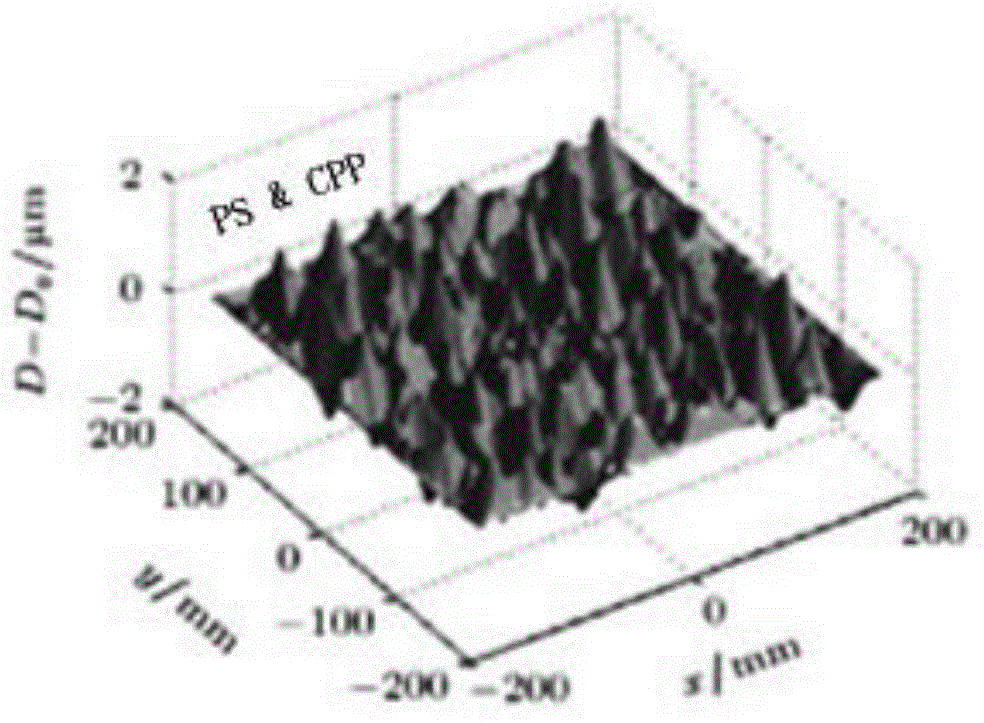
[0031] The present invention will be further described in detail below in conjunction with the accompanying drawings, so that those skilled in the art can implement it with reference to the description. For the sake of simplicity, CPP is used to represent the common continuous phase plate, CPP and PS are used to represent the combination of common continuous phase plate and polarization smooth crystal wedge, and PS&CPP is used to represent a kind of target focal spot shaping and beam uniformity of the present invention. Slide the phase plate in the laser beam path.

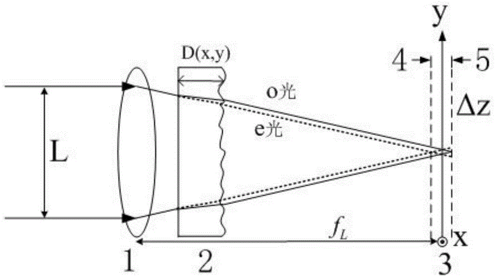
[0032] A laser optical path for target focal spot shaping and beam smoothing, such as figure 1 As shown, the incident light field L is perpendicular to the surface of the convex lens (1) and is focused by the convex lens (1) to form a focused beam. When the focused beam passes through PS&CPP (2), it is divided into ordinary light (o light) with equal intensity and extraordinary light (e light), and because there ...


PUM


Abstract

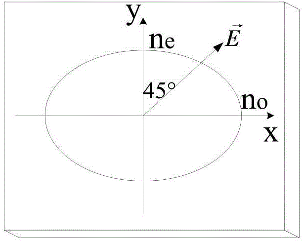
The invention discloses a laser optical path used for target focal spot shaping and beam smoothing. The laser optical path is characterized in that the laser optical path comprises an incident laser beam, a convex lens, a phase plate and a target surface; the phase plate is composed of a uniaxial crystal; front and rear surfaces of the phase plate are parallel to the optical axis of the uniaxial crystal; continuous phase plate surface shapes are etched on one of front and rear surfaces through the existing technology; when the incident laser beam comes into the optical path, the incident laser beam is perpendicular to the surface of the convex lens, and the polarization direction and the optical axis of the uniaxial crystal form an angle of 45 degrees; the phase plate is located between the lens and the target surface, and is near the side of the lens; and the surface, which is etched with the continuous phase plate surface shapes, of the phase plate is relative to the target surface. According to the invention, without reducing the performance of a laser driver, the functions of focal spot shaping and polarization smoothing are reserved; the combination of continuous phase plates and a polarization smoothing crystal plate is replaced; compared with the previous method, the laser optical path is more concise; the total thickness of the beam passing through an optical element is reduced; and the damage risk of the optical element can be effectively reduced.

Description

technical field [0001] The invention relates to an optical path system using laser far-field focal spot shaping technology and beam smoothing technology in a high-power solid-state laser driver, in particular to a laser optical path for target point focal spot shaping and beam smoothing. Background technique [0002] In high-power solid-state laser drivers, target focal spot shaping and smoothing are key technologies in laser-driven inertial confinement fusion (ICF) experiments. Whether in direct drive or indirect drive, in order to improve the irradiation uniformity of the target and reduce various instabilities in the process of laser plasma action, it is necessary to use the focal spot shaping and beam smoothing technology to obtain a specific shape of the laser focus. spot and maintain the shape and uniformity of the focal spot within a certain depth of focus. The current device used for focal spot shaping is continuous phase plate (CPP), whose principle is to add a spe...

Claims


Application Information

Patent Timeline
Patent Type & Authority Applications(China)
IPC IPC(8): G02B27/09G02B27/28
Inventor 耿远超李平张颖黄晚晴王文义刘兰琴粟敬钦郑万国
Owner LASER FUSION RES CENT CHINA ACAD OF ENG PHYSICS
Learn More