
Water injection device for a bypass steam system of a power plant

A technology of water spraying equipment and steam system, applied in steam superheating, mechanical equipment, steam generation, etc., can solve problems such as condenser damage, achieve good cooling effect, avoid accumulation, improve atomization and mixing effects

Inactive Publication Date: 2014-10-08
SIEMENS AG
View PDF7 Cites 2 Cited by
  • Summary
  • Abstract
  • Description
  • Claims
  • Application Information

AI Technical Summary

Problems solved by technology

Otherwise the condenser may be damaged

Method used


Image

  • Water injection device for a bypass steam system of a power plant
  • Water injection device for a bypass steam system of a power plant

Examples


Embodiment Construction

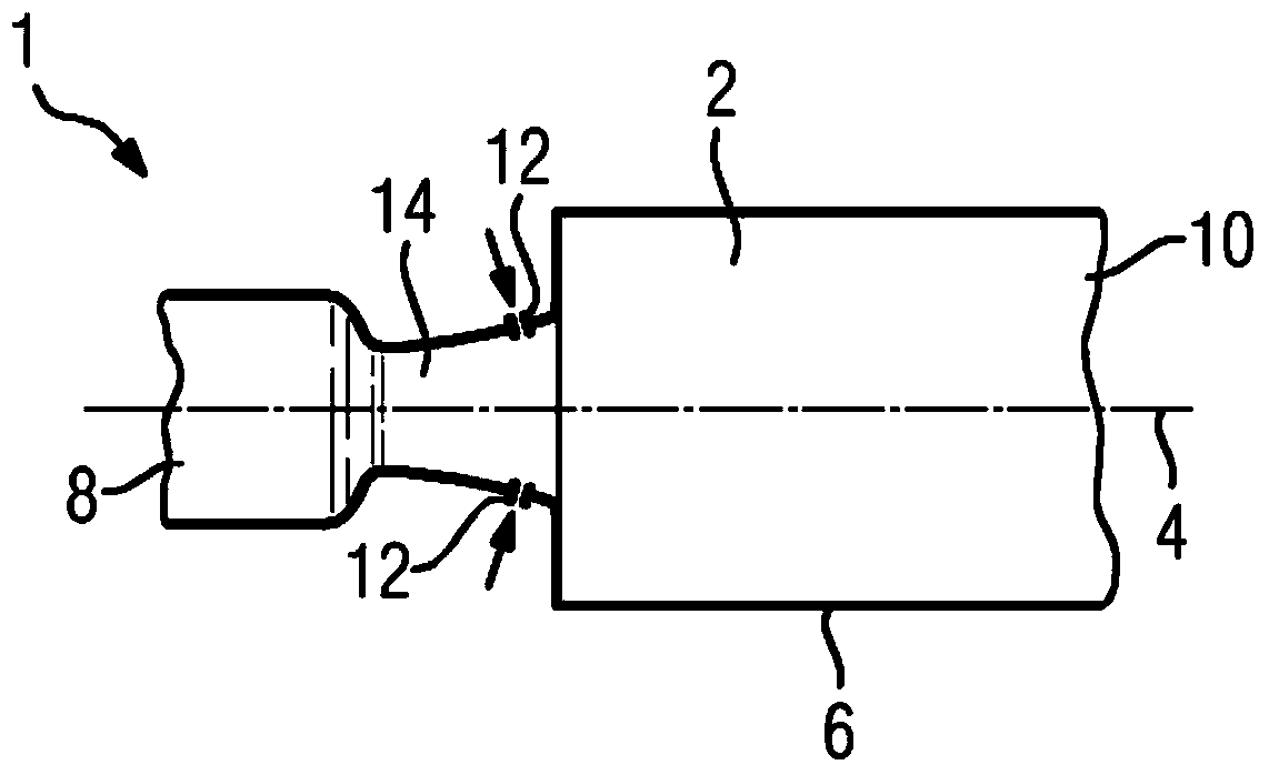
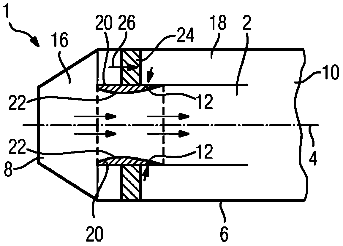
[0021] according to figure 1 The sprinkler device 1 comprises a flow channel 2 surrounded by an inner wall 6 arranged radially symmetrically about an axis 4 . Steam inlet 8 in figure 1 The center is on the left, and the steam outlet 10 is on the right. The cross section of the steam inlet 8 is smaller than the cross section of the steam outlet 10 . This achieves the effect that the underexpanded strands generated after the converging nozzle 14 do not touch the inner wall 6 .

[0022] The water injection system 1 is part of a bypass steam system of a power plant, which is not shown in detail. Not shown is a bypass valve connected upstream of the steam inlet 8, by means of which the steam flow from the steam generator of the power plant is directly introduced into the steam outlet 10 via the bypass steam system bypassing the steam turbine into the downstream condenser. This can be necessary in certain situations, for example when the steam turbine starts up or after a trip....


PUM


Abstract

A water injection device (1) for a bypass steam system of a power plant, comprising a flow channel (2) for steam with a steam inlet (8) and a steam outlet (10), and an injection nozzle (12) which is arranged between the steam inlet and outlet (8, 10), is to have a particularly satisfactory cooling action in order to avoid condenser damage by way of technically particularly simple means. To this end, the injection nozzle (12) is arranged on a wall (20) which extends substantially in the direction of the gas flow and is arranged spaced apart from an inner wall (6) of the flow channel (2).

Description

technical field [0001] The invention relates to a water spraying device for a bypass steam system of a power plant, said water spraying device comprising a flow channel for steam with a steam inlet and a steam outlet and a spray arranged between the steam inlet and the steam outlet nozzle. Background technique [0002] Power plants for the production of electrical energy typically use the thermal energy of the combustion process to produce mechanical energy, which is then converted into electrical energy in a generator. Usually, direct-fired steam generators are used here, which generate steam for the steam turbine. But the thermal energy used to generate steam can also be obtained from other sources, such as nuclear energy. Another way, not indirectly by generating steam, is to provide direct conversion, for example in a gas turbine. In this case, however, the hot exhaust gas of the gas turbine is usually additionally used in a waste heat boiler to generate steam. So in...

Claims


Application Information

Patent Timeline
Patent Type & Authority Applications(China)
IPC IPC(8): F22G5/12B01F5/04
CPCF22G5/123F16L41/02B01F5/048Y10T137/87571B01F25/31423
Inventor 弗兰克·戴斯特
Owner SIEMENS AG
Learn More