
Helium processing device of high yield neutron generator

A neutron generator and processing device technology, applied in nuclear technology and application fields, can solve problems such as vacuum drop, neutron yield reduction, insulation performance deterioration, etc., to achieve extended service life, increased yield, and low operating costs Effect

Inactive Publication Date: 2014-10-08
INST OF NUCLEAR PHYSICS & CHEM CHINA ACADEMY OF
View PDF5 Cites 4 Cited by
  • Summary
  • Abstract
  • Description
  • Claims
  • Application Information

AI Technical Summary

Problems solved by technology

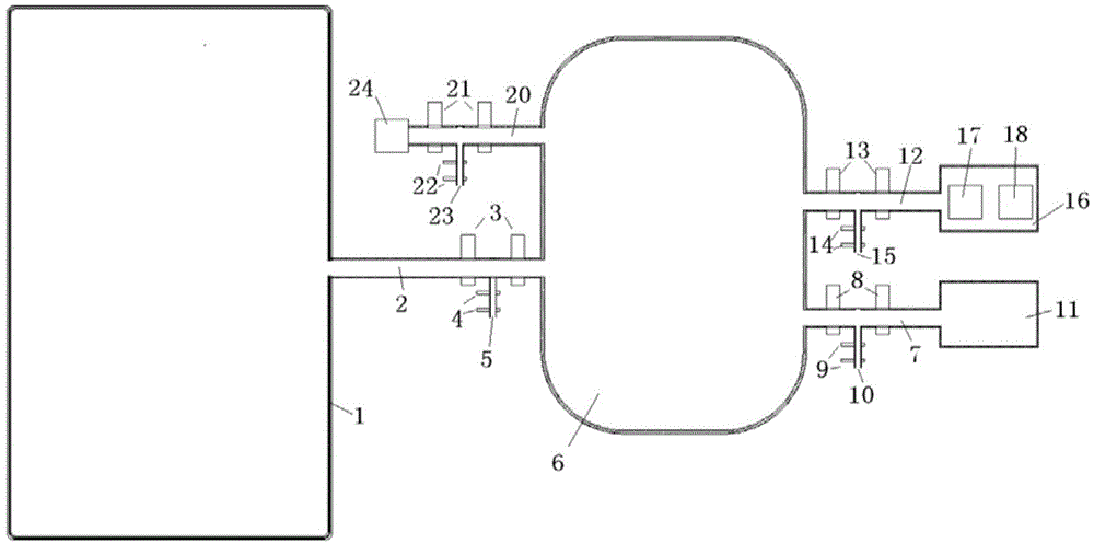
[0016] The technical problem to be solved by the present invention is to provide a helium treatment device for a high-yield neutron generator, which solves the problem of continuous accumulation of helium and other impurity gases in high-yield closed neutron generators, resulting in a drop in vacuum and a decrease in neutron yield , the problem of deterioration of insulation performance

Method used


Image

  • Helium processing device of high yield neutron generator

Examples


Embodiment 1

[0041] The size of the vacuum chamber of a high-yield neutron generator is 700mm×Φ300mm, the size of the target is 500×Φ10mm, and the volume of the vacuum system is about 50L. The deuterium-tritium gas pressure is 0.5Pa, the ratio is 1:1, using self-forming targets, and the neutron yield of deuterium-tritium reaction is 10 13 n / s.

[0042] Considering only the decay of gaseous tritium in the vacuum container of the main body of the neutron generator, the helium production rate is 8.6×10 10 n / s, the time required for the partial pressure of helium to reach 0.025Pa is about 700 hours. At this time, the partial pressure of helium is 5%, and the output drops by at least 5%. Part of the helium produced by the decay of tritium in other parts and the helium produced by the deuterium-tritium reaction enters the vacuum system in gaseous form, plus the O released by the materials bombarded by helium particles, deuterium ions and tritium particles. 2 and other impurity gases, the actua...

Embodiment 2

[0048] The main parameters of the neutron generator are the same as above. In order to increase the speed of removing helium and other impurity gases, or improve the stability of the neutron yield, the volume of the vacuum container of the helium processing system is changed to a cylindrical container with a diameter of 500mm and a height of 1000mm. About 200L, which is 4 times the vacuum volume of the neutron generator, and the volume of the vacuum connecting pipe can be ignored.

[0049] Considering only the decay of gaseous tritium in the vacuum container of the main body of the neutron generator, the helium production rate is 8.6×10 10 n / s, the time required for the partial pressure of helium to reach 0.025Pa is about 700 hours. At this time, the partial pressure of helium is 5%, and the output drops by at least 5%. Part of the helium produced by the decay of tritium in other parts and the helium produced by the deuterium-tritium reaction enters the vacuum system in gaseou...


PUM


Abstract

The invention discloses a helium processing device of a high yield neutron generator. The helium processing device is connected to a large-volume helium processing vacuum container through a vacuum pipeline outside a neutron generator main vacuum chamber. In the helium processing container, hydrogen absorption alloy which has large adsorbing capacity and high absorbing speed to deuterium and tritium gas, has low absorbing speed to non-hydrogen impurity gas, and does not have the absorbing effect on helium is used for absorbing the deuterium and tritium gas in a system, and remaining helium and non-hydrogen impurity gas are pumped by an ionic pump. Then, the hydrogen absorption alloy is appropriately heated, the absorbed deuterium and tritium gas is released to the inside of the vacuum container again, and the purposes that in the totally-sealed container, the deuterium and tritium gas is basically not consumed and meanwhile the helium and other impurity gas are dynamically eliminated are achieved. The helium processing device is particularly suitable for being used in totally-sealed deuterium and tritium neutron generators which has long service life and high yields.

Description

technical field [0001] The invention relates to the field of nuclear technology and application, in particular to a helium processing device for a high-yield deuterium-tritium neutron generator. Background technique [0002] Small-scale neutron generators are generally divided into radioactive source neutron generators and accelerator neutron generators. Radioactive source neutron generators use radionuclides to generate neutrons, with low output and short life. The neutron generator of the accelerator has a high output, no neutrons are generated after the power is turned off, it is easy to use, has good controllability and high safety. [0003] The accelerator neutron generator uses the deuterium or deuterium-tritium mixed ions generated by the ion source. After being accelerated by the accelerating electric field, it obtains higher energy, and deuterium / deuterium or deuterium / tritium fusion reactions occur on the target, releasing medium in the direction of 4π. particles ...

Claims


Application Information

Patent Timeline
IPC IPC(8): H05H6/00H05H3/06
Inventor 何小海李彦薛小明娄本超唐君张钦龙刘百力刘湾黄瑾李艳
Owner INST OF NUCLEAR PHYSICS & CHEM CHINA ACADEMY OF
Learn More