
Intelligent lighting germicidal lamp and circuit control method thereof

A technology of intelligent lighting and germicidal lamps, applied in energy-saving control technology, lamp circuit layout, lighting devices, etc., can solve the problems of inability to automatically control lighting and sterilization time, and achieve the effect of ensuring the killing of bacteria and increasing the irradiation time

Inactive Publication Date: 2014-10-08
刘德权
View PDF6 Cites 13 Cited by
  • Summary
  • Abstract
  • Description
  • Claims
  • Application Information

AI Technical Summary

Problems solved by technology

None of the above existing technologies can automatically control lighting and sterilization time according to the needs of different environments by presetting

Method used


Image

  • Intelligent lighting germicidal lamp and circuit control method thereof
  • Intelligent lighting germicidal lamp and circuit control method thereof
  • Intelligent lighting germicidal lamp and circuit control method thereof

Examples


Embodiment 1

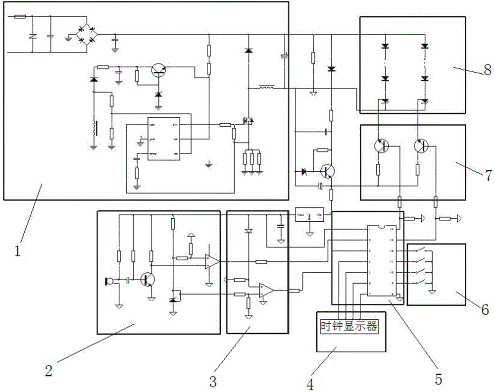
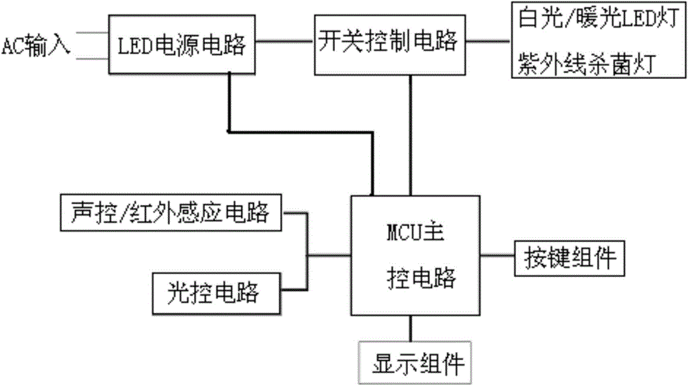
[0042] Such as figure 2 , image 3 As shown, a kind of intelligent lighting sterilizing lamp comprises LED power supply circuit 1, switch control circuit 8, white light / warm light LED lamp for lighting (i.e. image 3 white light / warm light LED lamp), ultraviolet germicidal lamp (ordinary ultraviolet germicidal lamp or LED ultraviolet germicidal lamp), MCU main control circuit 5, sound control / infrared induction circuit 2, light control circuit 3, button assembly 6 and display assembly 4 , the white light / warm light LED lamp for lighting and the ultraviolet sterilizing lamp are connected in parallel to form a light module circuit 7, and the LED power supply circuit, switch control circuit, and light module circuit are connected in series in sequence; the LED power supply circuit and switch control circuit are all connected to the MCU main control circuit. The LED power supply circuit is used to provide working voltage for the entire intelligent lighting sterilization lamp; t...

Embodiment 2

[0053] Such as Figure 4 to Figure 14 As shown, further improvements are made on the basis of the foregoing embodiments. Intelligent lighting sterilization lamps, including MCU power supply circuit (LED power supply circuit), light control circuit (switch control circuit), white light module circuit (including white light / warm light LED lamp for lighting), LED / ordinary ultraviolet light module (including ultraviolet germicidal lamp ), MCU main control circuit, human body induction circuit (infrared induction circuit), sound control / light control circuit, button circuit, display circuit, clock circuit and remote control signal circuit. The MCU power supply circuit, light control circuit, human body induction circuit, sound control / light control circuit, button circuit, display circuit, clock circuit and remote control signal circuit are all connected to the MCU main control circuit. The white light module circuit and the LED / common ultraviolet light module are all connected to...


PUM


Abstract

The invention discloses an intelligent lighting germicidal lamp and a circuit control method thereof. The intelligent lighting germicidal lamp comprises an LED power circuit, a lamp control circuit, a white light / warm light LED lamp for lighting, a key assembly, a display assembly, a sound control / infrared induction circuit, a light control circuit, an ultraviolet germicidal lamp and an MCU master control circuit. The white light / warm light LED lamp for lighting and the ultraviolet germicidal lamp are connected in parallel to form a lamplight module circuit. The LED power circuit, the lamp control circuit and the lamplight module circuit are in series connection sequentially. The lamp control circuit is connected with the MCU master control circuit. According to the circuit control method of the intelligent lighting germicidal lamp, automatic lighting and germicidal functions are achieved through the circuits. According to the intelligent lighting germicidal lamp, the commonly-used white light / warm light LED lamp for lighting and the ultraviolet germicidal lamp are integrated, and the germicidal and lighting functions can be achieved without manual on-off control.

Description

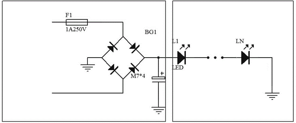
technical field [0001] The invention relates to the field of LED lighting fixtures, in particular to a germicidal lamp with efficient and intelligent lighting functions. Background technique [0002] At present, in addition to conventional germicidal lamps on the market (this kind of lamp has a short lifespan, high power and is not environmentally friendly and toxic), there are also LED lamps specially used for germicidal lamps. Although this kind of lamp has a sterilizing effect, But it can't play the role of lighting, and it needs to be manually switched to achieve. And the application of lamps and lanterns is single, there is certain limitation. Such as figure 1 As shown, it is an ordinary germicidal lamp in the prior art. The input alternating current is simply rectified and then supplied to an LED lamp that can emit ultraviolet light, so as to play a sterilizing role. [0003] In the prior art, the invention with application number 201010143103.5 discloses an LED con...

Claims


Application Information

Patent Timeline
Patent Type & Authority Applications(China)
IPC IPC(8): H05B37/02
CPCY02B20/40
Inventor 刘德权曹承朝汪荣华
Owner 刘德权
Learn More