
Method and system for mixed refrigerant gas-liquid split throttling refrigeration

A mixed refrigerant and split-flow technology, which is applied in refrigeration and liquefaction, cold treatment separation, liquefaction, etc., can solve high-cost problems that can only be used in a small number of small-scale liquefaction devices and offshore floating liquefaction devices, and achieve low operating costs and low investment. Energy saving and high energy efficiency

Active Publication Date: 2017-11-17
BEIJING MEIHUASHENG ENG TECH
View PDF12 Cites 0 Cited by
  • Summary
  • Abstract
  • Description
  • Claims
  • Application Information

AI Technical Summary

Problems solved by technology

The expander cycle process is the simplest, with less equipment and the least investment. However, the energy consumption of this process is the highest among all technologies, and it can only be applied in a small number of small-scale liquefaction units and offshore floating liquefaction units.

Method used


Image

  • Method and system for mixed refrigerant gas-liquid split throttling refrigeration

Examples


Embodiment 1

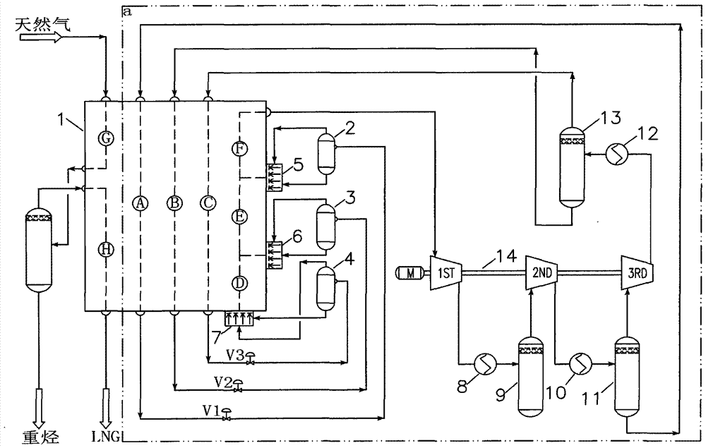
[0036] For the specific process flow of this embodiment, please refer to figure 1 .

[0037]A mixed refrigerant gas-liquid split throttling refrigeration system, comprising: a mixed refrigerant compressor 14, a first-stage outlet cooler 8, a second-stage inlet buffer tank 9, a second-stage outlet cooler 10, and a third-stage inlet separator 11 , three-stage outlet cooler 12, three-stage outlet separator 13, the first flow channel A, the second flow channel B, the third flow channel C, the fourth flow channel D, the fifth flow channel E, and the sixth flow channel of the cold box 1 Channel F, first separator 2, second separator 3, third separator 4, first throttle valve V1, second throttle valve V2, third throttle valve V3, first static mixer 5, The second static mixer 6 and the third static mixer 7, wherein the inlet of the first section of the mixed refrigerant compressor 14 is connected to the outlet of the sixth channel F of the cold box 1, and the outlet is followed by th...

Embodiment 2

[0041] For the specific process flow of this embodiment, please refer to figure 1 .

[0042] As shown in the device, the first-stage outlet cooler 8, the second-stage outlet cooler 10 and the third-stage outlet cooler 12 are air coolers, and the mixed refrigerant compressor 7 is a centrifugal compressor.

[0043] The low-pressure mixed refrigerant I from the cold box enters the first stage of the mixed refrigerant compressor 14 at a flow rate of 171920kg / h to be compressed and boosted to 1000kPa, and then cooled to 45°C through the first-stage outlet cooler 8 to obtain the mixed refrigerant II; the mixed refrigerant Agent II enters the mixed refrigerant compressor 14 through the second-stage inlet buffer tank 9 to be compressed and pressurized to 2400kPa in the second-stage, and then is cooled to 45°C through the second-stage outlet cooler 10 and sent to the third-stage inlet separator 11, and the liquid is obtained after separation. Phase mixed refrigerant III and gas phase ...

Embodiment 3

[0046] For the specific process flow of this embodiment, please refer to figure 1 .

[0047] As shown in the figure, the first-stage outlet cooler 8 and the second-stage outlet cooler 10 are air coolers, the third-stage outlet cooler 12 is a shell-and-tube heat exchanger, and the mixed refrigerant compressor 7 is a screw compressor.

[0048] The low-pressure mixed refrigerant I from the cold box enters the first stage of the mixed refrigerant compressor 14 at a flow rate of 17200kg / h to be compressed and boosted to 400kPa, and then cooled to 40°C through the first-stage outlet cooler 8 to obtain the mixed refrigerant II; the mixed refrigerant Agent II enters the mixed refrigerant compressor 14 through the second-stage inlet buffer tank 9 to be compressed and pressurized to 900kPa in the second stage, and then is cooled to 40°C through the second-stage outlet cooler 10 and sent to the third-stage inlet separator 11, and the liquid is obtained after separation. Phase mixed refr...


PUM


Abstract

The invention relates to a mixed refrigerant gas-liquid separating type throttling and refrigerating method and system. According to the mixed refrigerant gas-liquid separating type throttling and refrigerating method and system, the advantages of the traditional refrigerating technology are utilized; in addition, gas-liquid separation is conducted on the mixed refrigerant between mixed refrigerant compressors and outlets of the mixed refrigerant compressors in a step-by-step mode, and all mixed refrigerant flows obtained after separation directly enter different flow channels in a cold box for undercooling and throttling, wherein gas-phase refrigerant flows are reheated to minus 12 DEG C to minus 40 DEG C firstly, secondly, the gas-phase refrigerant flows and the liquid-phase refrigerant flows are mixed one by one so that coldness can be provided for the cold box, and finally, the gas-phase refrigerant flows are reheated to minus 32 DEG C to 45 DEG C and flow out of the cold box to be delivered to inlets of the compressors so as to enter next refrigeration circulation. By the adoption of the mixed refrigerant gas-liquid separating type throttling and refrigerating method and system, the temperature gradient existing during refrigeration of the mixed refrigerant is increased, the energy efficiency is approximate to that achieved through a traditional stepwise refrigeration technology, and the simple flow process similar to that of the single-circulation refrigeration technology can be guaranteed at the same time; the energy consumption is low, the technology is simple, the variable-working condition adaptability is high, and the operability is high.

Description

technical field [0001] The invention relates to the field of liquefied natural gas production, in particular to a mixed refrigerant gas-liquid split flow throttling refrigeration method and system. Background technique [0002] Natural gas, as a clean and high-quality energy source, is rapidly expanding with the development of my country's economy and the improvement of environmental protection requirements. Due to the huge advantages of liquefied natural gas (LNG) in natural gas storage and transportation, liquefied natural gas is gradually becoming the first choice for natural gas demand. [0003] The core issue of LNG development lies in natural gas liquefaction technology. At present, there are generally three natural gas liquefaction processes commonly used at home and abroad: cascade cycle process, mixed refrigerant cycle process and expander cycle process. The cascade circulation process is the most successful dual refrigeration COPOC technology established by Conoc...

Claims


Application Information

Patent Timeline
Patent Type & Authority Patents(China)
IPC IPC(8): F25J1/02
CPCF25J1/0055F25J1/0022F25J1/0212F25J2220/64
Inventor 张会军王道广王英军
Owner BEIJING MEIHUASHENG ENG TECH
Learn More