
A kind of control method of vibration system

A control method and vibration system technology, applied in the field of construction machinery, can solve the problems of increasing user operating costs, increasing energy consumption, and high noise levels, and achieving the effects of improving efficiency, reducing rotational speed, and reducing emissions

Active Publication Date: 2016-08-10
XCMG CONSTR MACHINERY
View PDF5 Cites 0 Cited by
  • Summary
  • Abstract
  • Description
  • Claims
  • Application Information

AI Technical Summary

Problems solved by technology

The highest efficiency point of the hydraulic two-way plunger pump is at the maximum displacement value, which leads to a decrease in the efficiency of the hydraulic two-way plunger pump in the hydraulic vibration system when the vibratory roller is operating, and the engine needs to run at high speed, which increases energy consumption and lowers the noise level. High, and increase the operating cost of the user

Method used


Image

  • A kind of control method of vibration system

Examples


Embodiment Construction

[0018] The present invention will be further described below in conjunction with accompanying drawing.

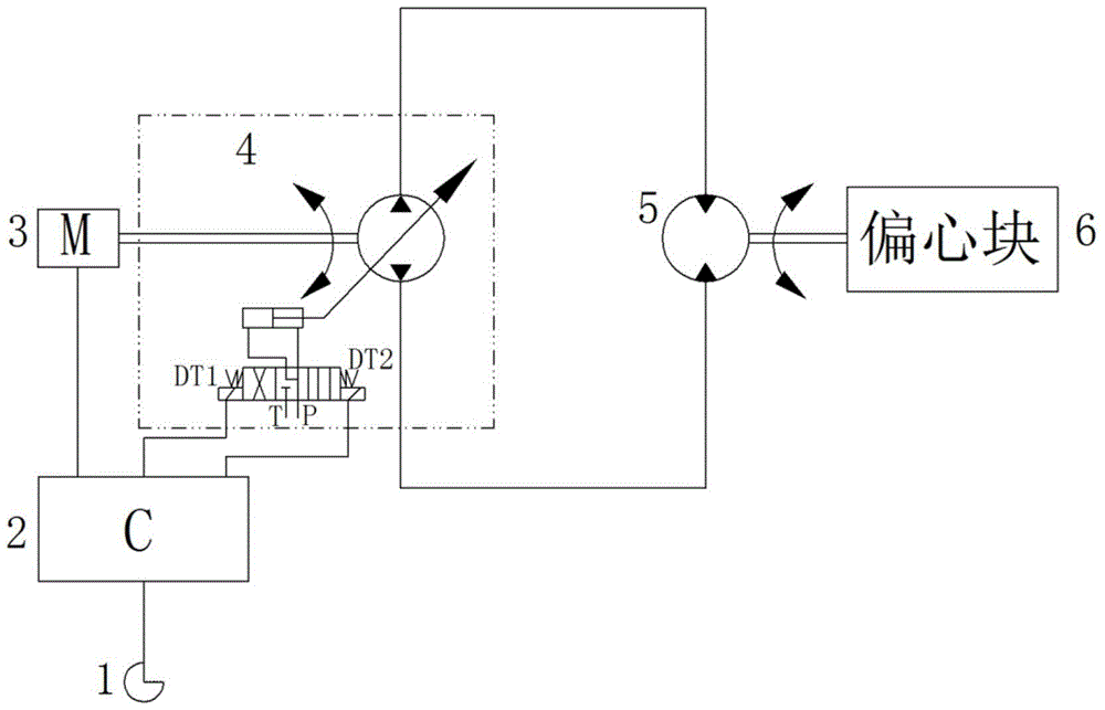
[0019] A vibration system includes an electronically controlled engine 3 , a hydraulic two-way plunger pump 4 , a hydraulic two-way plunger motor 5 , a controller 2 , and a vibration handle (knob) 1 .

[0020] The hydraulic two-way plunger pump 4 is connected in parallel with the hydraulic two-way plunger motor 5 to form a closed hydraulic circuit. The electric control engine 3 directly drives the hydraulic two-way plunger pump 4, and the hydraulic two-way plunger pump 4 supplies high-pressure oil to the hydraulic circuit to drive the hydraulic two-way The plunger motor 5 rotates, the vibration handle (knob) 1 is electrically connected with the controller 2, and transmits the operation mode information to the controller 2; DT2 is electrically connected. The controller 2 controls the rotation speed of the electronically controlled engine 3 and the power gain and loss of the...


PUM


Abstract

The invention relates to a control method of a vibration system. The control method comprises the following steps: (1) The operator sets the high-frequency low-amplitude operation mode or the low-frequency high-amplitude operation mode through the vibration handle; (2) The vibration handle transmits to the controller Operation mode information; (3) When high-frequency and low-amplitude operations are performed, the controller sends a signal to control the solenoid valve DT1 of the hydraulic two-way plunger pump to be energized and the solenoid valve DT2 to be de-energized, so that the displacement on one side of the hydraulic two-way plunger pump is at Maximum value; when working at low frequency and high amplitude, the controller sends a signal to control the solenoid valve DT2 of the hydraulic two-way plunger pump to be energized and the solenoid valve DT1 to be de-energized, so that the displacement on the other side of the hydraulic two-way plunger pump is at the maximum value; ( 4) The controller sends a signal to adjust the speed of the electronically controlled engine, so that the electronically controlled engine runs at a low speed to ensure the operating frequency of the road roller. The invention can make the engine work at a low speed, the displacement of the two-way plunger pump is at the maximum value, improve the efficiency of the vibration system of the road roller, save energy and reduce emissions, and reduce the operating cost of users.

Description

technical field [0001] The invention belongs to the technical field of engineering machinery, and in particular relates to a control method of a vibration system. Background technique [0002] At present, the vibration system of the vibratory roller generally adopts a closed circuit composed of a hydraulic two-way plunger pump and a hydraulic two-way plunger motor. The hydraulic two-way plunger motor drives the eccentric block in the vibrating wheel of the vibratory roller to realize the vibration function. The power source of the circuit is For an engine operated by a flexible shaft, the engine speed cannot be adjusted arbitrarily. Since the matching of the hydraulic vibration system cannot make the displacement of the hydraulic two-way plunger pump at the maximum value, it is necessary to adjust the displacement limiter of the hydraulic two-way plunger pump to reduce the displacement value when the engine speed is constant, so as to ensure that the roller frequency of wor...

Claims


Application Information

Patent Timeline
Patent Type & Authority Patents(China)
IPC IPC(8): E01C19/28
Inventor 张帅张俊娴朱信强肖洋位文凯唐景文
Owner XCMG CONSTR MACHINERY
Learn More