Eureka AIR delivers breakthrough ideas for toughest innovation challenges, trusted by R&D personnel around the world.

Spine osteotomy bone knife

A bone knife and spine technology, applied in the field of medical equipment, can solve problems such as easy misalignment, touching the spinal cord, and paralysis of patients, and achieve the effects of improving safety, increasing stability, and avoiding looseness

Inactive Publication Date: 2014-10-08
陶惠人 +1
View PDF5 Cites 0 Cited by
  • Summary
  • Abstract
  • Description
  • Claims
  • Application Information

AI Technical Summary

Problems solved by technology

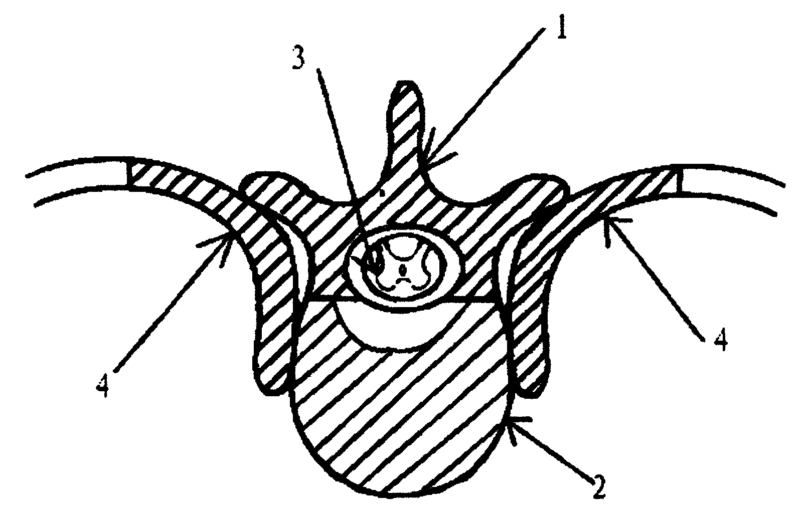
When using the conventional bone knife or drill to remove the remaining part of the vertebral body 2, since the upper part of the vertebral body 2 is the spinal cord, if there is a slight deviation during the operation, the spine knife or the drill will touch the spinal cord paralyzed the patient
Figure 5 It is a schematic diagram of the structure of a common bone knife in the prior art, such as Figure 5 As shown, the existing common bone knife includes a knife handle 14, a knife bar 12, and a knife head 11, wherein the knife handle 14 and the knife bar 12 are fixed as a whole by screws 13, and the knife head 11 and the knife bar 12 are linear , and the end of its cutter head is rectangular; when using the common osteotome of prior art to carry out osteotomy to spinal column, because cutter head 11 and cutter bar 12 are on the same straight line, and its two ends have pointed parts, like this The bone knife of the structure is easy to touch the nerves around the spinal bone during the operation, and the knife handle 14 and the knife bar 12 are fixed as a whole by screws 13. When used for too long, the gap between the knife handle 14 and the knife bar 12 There will be looseness during the operation, and after the loosening, it is easy to cause dislocation during the operation, and the dislocation is extremely easy to cause the spinal cord to be touched, and once the spinal cord is touched, the spinal cord may be damaged, which may lead to paralysis of the patient

Method used


Image

  • Spine osteotomy bone knife
  • Spine osteotomy bone knife
  • Spine osteotomy bone knife

Examples


Embodiment Construction

[0015] In order to make the purpose, technical solutions and advantages of the present invention clearer, the technical solutions in the present invention will be clearly and completely described below in conjunction with the accompanying drawings in the present invention. Obviously, the described embodiments are part of the embodiments of the present invention , but not all examples. Based on the embodiments of the present invention, all other embodiments obtained by persons of ordinary skill in the art without creative efforts fall within the protection scope of the present invention.

[0016] Image 6 It is a schematic diagram of the structure of the spinal osteotomy osteotome of the present invention, as Image 6 As shown, the spinal osteotomy osteotome of the present invention includes a cutter head 11 , a cutter bar 12 , and a handle 14 . Wherein, the cutter head 11 is arranged at the end of the cutter rod 12, and the cutter rod 12 and the handle 14 are poured into an ...


PUM


Abstract

The invention provides a spine osteotomy bone knife which comprises a cutter head, a cutter rod and a cutter handle, wherein the cutter head is arranged at the end part of the cutter rod; the cutter head is provided with a first end part and a second end part; the cutter rod and the first end part are L-shaped; the blade is arranged on the edge of the first end part; the cutter rod and the cutter handle are of an integrated structure in a filling-casting manner. According to the spine osteotomy bone knife, the cutter rod and the first end part are L-shaped, the first end part and the second end part are L-shaped, the first end part is used for cutting the bone across the spinal cord of the spine, the first end part and the second end part are clamped in the bone cutting position of the spine bone, and the stability of the spine osteotomy bone knife in the surgery process is improved; on the other hand, the cutter rod and the cutter handle are of the integrated structure in the filling-casting manner, the loose of the spine osteotomy bone knife after being used for a too long time is avoided, and the security of the spine osteotomy bone knife in surgery is further improved.

Description

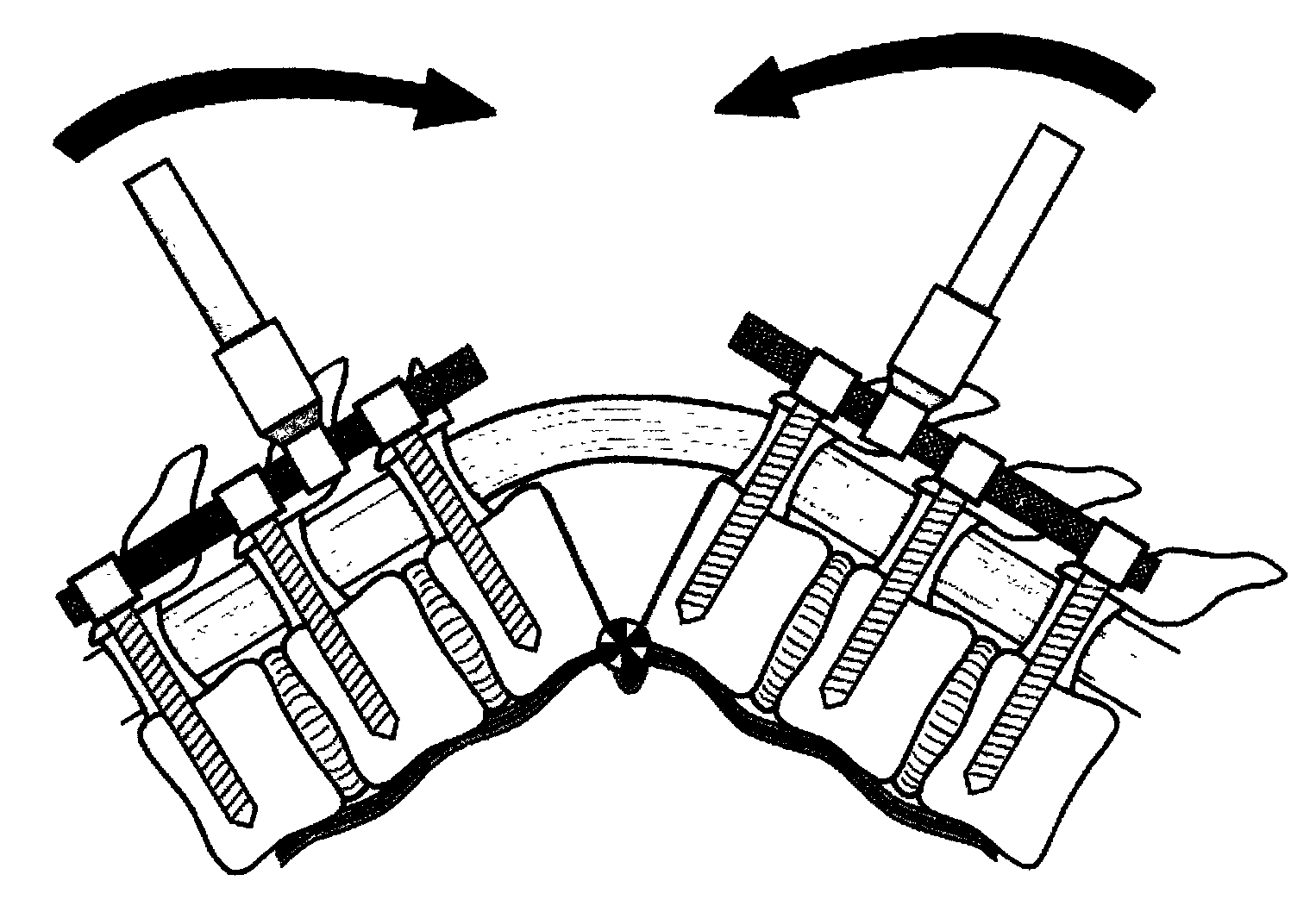
technical field [0001] The invention relates to the field of medical instruments, in particular to a spinal osteotomy osteotome. Background technique [0002] In the surgery to correct spinal deformity, firstly, the curved spinal bone is removed by osteotomy with a scalpel. figure 1 Schematic diagram of the outline of the spine in the lesion state, figure 2 Schematic diagram of the cross-sectional structure of the spine; figure 1 As shown, the curvature of the spine is relatively serious, and in order to correct the curved spine, the usual surgical approach is to first figure 2 The shadow part of the middle pedicle 1 and rib 4 was bitten off with a rongeur, and then the shadow part of the vertebral body 2 was removed using a common bone knife or drill in the prior art, and finally the remaining part of the vertebral body 2 was removed. And because of the developmental deformity of the spine and the obstruction of the spinal cord, the remaining part of the vertebral body...

Claims


Application Information

Patent Timeline
Patent Type & Authority Applications(China)
IPC IPC(8): A61B17/3211A61B17/56
CPCA61B17/1671
Inventor 陶惠人沈超
Owner 陶惠人
Why Eureka
Eureka Blog
Learn More