Temple device for towel loom

A technology for towel looms and temples, which is applied in textiles, textiles, papermaking, and auxiliary equipment for weaving. It can solve problems such as frequent maintenance, fabric surface damage, and short service life of parts, so as to reduce use and maintenance costs. Effect of improving fabric quality and prolonging service life

Active Publication Date: 2015-08-26
SHANDONG RIFA TEXTILE MACHINERY
View PDF8 Cites 0 Cited by
  • Summary
  • Abstract
  • Description
  • Claims
  • Application Information

AI Technical Summary

Problems solved by technology

The towel looms in the prior art usually adopt a fixed temple device structure, and the existing defect is that due to the movement of the weaving fell in the production of towel fabric, friction between the fabric and the temple device will inevitably occur, resulting in damage to the fabric surface , affecting fabric quality
[0003] In addition, on the towel loom when weaving high-grade terry fabrics, the knot of the prior art aims to solve the above-mentioned problems in the prior art. The movement is realized, and the movement of the side stay is driven by the cloth moving transmission device. The structure of the cloth moving transmission device of the prior art towel loom is usually that the swing rod drives the slide plate through the rocker, and the side stay rod is connected on the slide plate, and the swing of the swing rod Converted to the movement of the side stay, the movement of the skateboard is sliding friction. The disadvantages are that the friction force is large, the power consumption is large, and the movement track of the rocker arm has a certain arc, so that the movement of the sliding block is not a straight line movement. , The sliding block is prone to deformation, resulting in a short service life of the parts, requiring frequent maintenance, affecting the weaving efficiency of the loom, and increasing the use and maintenance costs

Method used


Image

  • Temple device for towel loom
  • Temple device for towel loom
  • Temple device for towel loom

Examples


Embodiment Construction

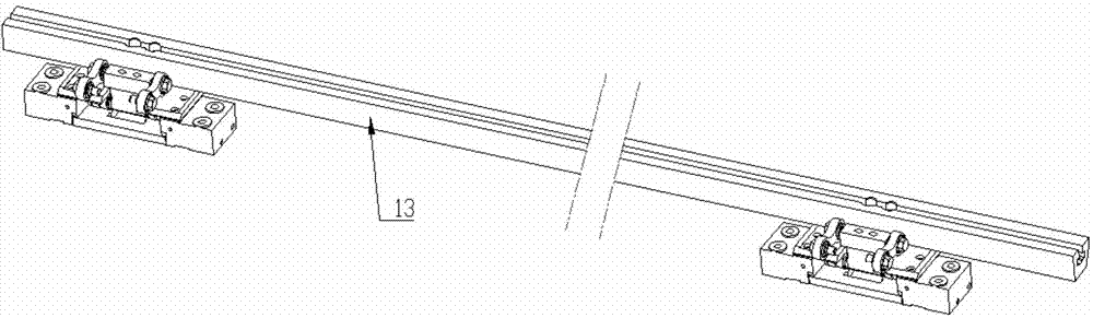
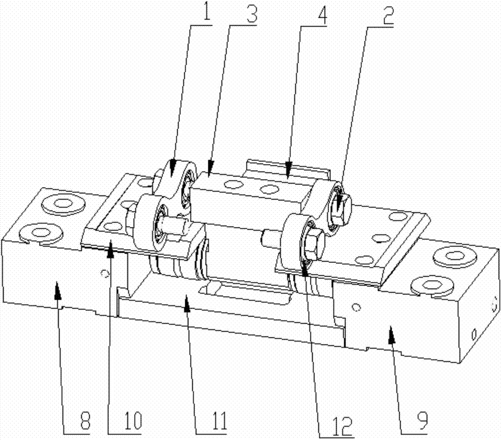
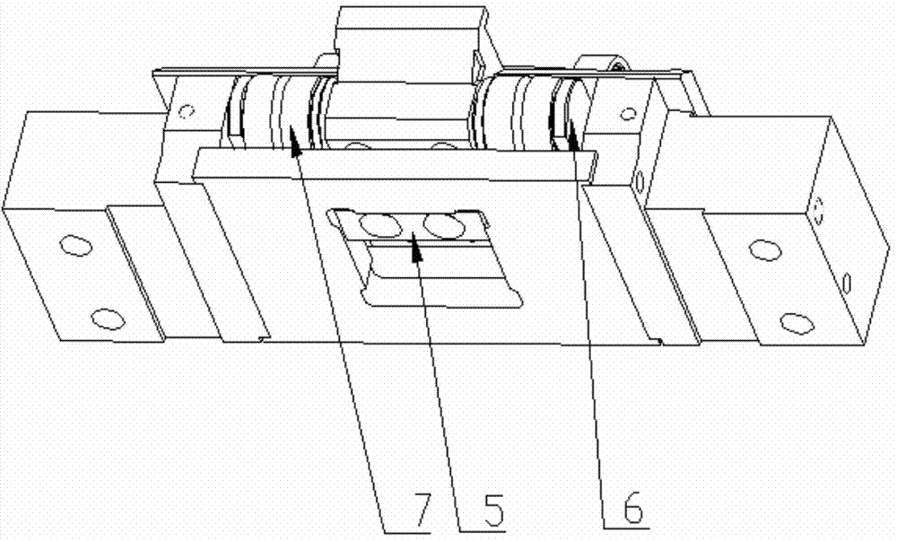
[0020] In order to better understand the present invention, the implementation manner of the present invention will be explained in detail below in conjunction with the accompanying drawings.

[0021] combine as Figure 1 to Figure 5 , a temple device for a towel loom, comprising a reciprocating part and a fixed part, the reciprocating part reciprocates along the fixed part, and the reciprocating part includes a push arm 1, a push block 3, and a slider holder 4 , sliding limit block 5, slide bar pin 6, needle roller bearing 7 and sliding seat 13, the both sides of described push block 3 are respectively provided with a push arm 1, and the inner hole of described push arm 1 is provided with centripetal Joint bearing 12, one end of push arm 1 is connected with push block 3 by follower pin 2, and the other end of push arm 1 is connected with the power output end of loom raising mechanism; Described push block 3, slide seat 13 are connected with slide seat respectively The holder...


PUM


Abstract

The invention discloses a side supporting device for a terry cloth loom. The side supporting device comprises a push block, a slide bar pin, a needle bearing, a sliding seat, a left sliding seat support, a right sliding seat support, guide rails and a sliding pedestal, wherein two sides of the push block are respectively provided with a push arm which is provided with a centripetal joint bearing, and the push arms are connected to the push blocks while the other end of each push arm is connected to a power output end; the push block and the sliding seat are respectively fixedly connected to a sliding seat holder, and the sliding limiting block is arranged on the bottom surface of the sliding seat holder; the sliding pedestal is connected to the left sliding seat support and the right sliding seat support respectively, the left and right sliding seat supports are connected to the loom, the guide rails are arranged on the top surface of the left and right sliding seat supports, the guide rails and the upper plane of the sliding pedestal are matched with the needle bearing, the sliding pedestal is provided with a middle groove, and the sliding limiting block is matched with the middle groove and move back and forth along the middle groove. The device moves synchronously with the cloth-fell, is high in reliability and prevents quality of fabric being influenced due to that the surface of fabric is damaged by rub between the fabric and the side supporting device.

Description

technical field [0001] The invention relates to the technical field of textile equipment, in particular to a temple device for a towel loom. Background technique [0002] When weaving towel fabric, the first two weft yarns of a looping weft cycle keep a certain distance from the fabric fell, and when the third weft of the looping weft cycle is entered, the fabric fell moves toward the reed, and a looping weft cycle The three weft yarns in the fabric are driven into the fabric fell together, and the wool warp yarns are clamped by the ground warp yarns to form loops, forming a towel fabric. In order to tighten the weft yarn and prevent the cloth from shaking, a temple device is installed on the loom to support the cloth. The towel looms in the prior art usually adopt a fixed temple device structure, and the existing defect is that due to the movement of the weaving fell in the production of towel fabric, friction between the fabric and the temple device will inevitably occur,...

Claims


Application Information

Patent Timeline
Patent Type & Authority Patents(China)
IPC IPC(8): D03J1/22
Inventor 王建岭满富来吉学齐刘伟王涛
Owner SHANDONG RIFA TEXTILE MACHINERY
Why Eureka
Try Eureka