A cutting system with a vacuum stabilizing device

A voltage stabilizing device and cutting system technology, applied in grinding/polishing safety devices, grinding machine parts, grinding machines, etc. Unsmooth and other problems, to achieve the effect of enhancing the voltage stabilization effect, speeding up the falling, and convenient processing

Inactive Publication Date: 2017-03-15
SUZHOU KAIDE MICRO ELECTRONICS CO LTD
View PDF7 Cites 0 Cited by
  • Summary
  • Abstract
  • Description
  • Claims
  • Application Information

AI Technical Summary

Problems solved by technology

However, during the cutting process, the coolant is often relied on to take away the frictional heat between the cutting tool and the material to be cut, and the coolant is easy to flow into the vacuum tube through the vacuum adsorption piece, resulting in poor air path and unstable vacuum degree
Once the vacuum is unstable and the adsorption of the material to be cut is not firm, it is easy to cause the material to fly out, injuring the operator, cutting tools and cutting through the material.

Method used


Image

  • A cutting system with a vacuum stabilizing device
  • A cutting system with a vacuum stabilizing device
  • A cutting system with a vacuum stabilizing device

Examples


Embodiment 1

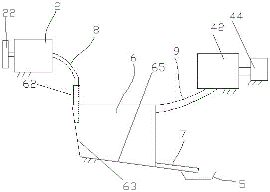
[0025] Such as figure 1 As shown, a cutting system with a vacuum stabilizing device includes a cutting machine 2 and a vacuuming device connected to the cutting machine 2, and also includes a vacuum stabilizing device connected to the cutting machine 2 and the vacuuming device.

[0026] The cutting machine 2 specifically includes a cutting tool (not shown) and a vacuum absorber 22 communicated with a vacuum device. Specifically, the vacuum absorber 22 may be a vacuum chuck. The vacuum suction cup is responsible for absorbing and fixing the material to be cut, and the cutting tool performs half-cut processing.

[0027] The vacuuming equipment includes a vacuum generator 42 and an air compressor 44 connected to the cutting machine 2 through a vacuum stabilizing device in sequence. After the air compressor 44 and the vacuum generator 42 are started, a negative pressure can be formed between the vacuum absorber 22 and the material to be cut, thereby absorbing the material to be c...

Embodiment 2

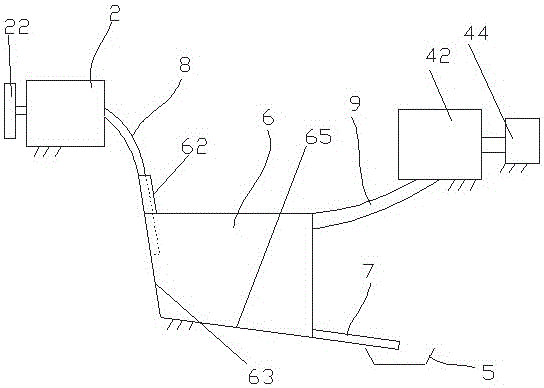
[0031] Such as figure 2 As shown, a cutting system with a vacuum stabilizing device differs from Embodiment 1 in that: the axis of the air inlet pipe 62 provided on the top of the casing 6 is parallel to the direction of inclination of the flow guide surface 63 and is close to the flow guide surface 63 set up. The first vacuum pipe 8 extends into the air intake pipe 62 and is connected with the air intake pipe 62 , while the lower end exposes the air intake pipe 62 and adjoins the guide surface 63 .

[0032] During operation, the coolant flows from the first vacuum pipe 8 extending into the intake pipe 62 to the guide surface 63, and the flow angle remains constant, falling continuously, smoothly and quickly.

Embodiment 3

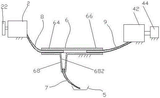
[0034] Such as image 3 As shown, a cutting system with a vacuum stabilizing device differs from Embodiment 1 in that: the housing 6 is in the shape of a three-way pipe, including a first branch pipe 64 and a second branch pipe 66 whose axes are respectively horizontal, and also includes The third branch pipe 68 in the vertical direction. The first, second and third branch pipes 64, 66 and 68 communicate with each other, and the axes of the first and second branch pipes 64 and 66 are on the same horizontal line. The nozzle of the first branch pipe 64 is an air inlet, and the cutting machine 2 is connected to the first branch pipe 64 by the first vacuum tube 8, and the first vacuum pipe 8 stretches into the first branch pipe 64 to the nozzle and is positioned above the nozzle of the third branch pipe 68; The nozzle of the second branch pipe 66 is an air outlet, and the vacuum equipment is connected to the second branch pipe 66 by a second vacuum tube 9; Conical funnel shape, ...


PUM


Abstract

The invention discloses a cutting system with a vacuum voltage stabilizer, which comprises a cutting machine, vacuum extraction equipment, and the vacuum voltage stabilizer communicating the cutting machine with the vacuum extraction equipment, wherein the vacuum voltage stabilizer comprises a hollow and sealed shell; an air inlet communicated with a vacuum adsorption piece, an air outlet communicated with the vacuum extraction equipment, and a water outlet formed below the air inlet and the air outlet are formed in the casing; the shell is provided with an oblique side wall; a diversion surface is formed below the air inlet. The cutting system is specially added with the vacuum voltage stabilizer, so that cooling liquid entering from the air inlet falls down, is separated from air under the effect of gravity, and discharged from the water outlet below. The cutting system is simple in structure, convenient to process, lower in cost and remarkable in voltage stabilization effect, can realize the purpose of voltage stabilization by utilizing the property of liquid, has no other energy consumption, and can greatly improve the cutting quality; the diversion surface is particularly arranged to direct the cooling liquid to rapidly fall down and be discharged to strengthen the voltage stabilization effect.

Description

technical field [0001] The invention relates to a cutting system and belongs to the technical field of mechanical processing. Background technique [0002] One type of cutting system, such as a grinding wheel scribing machine, includes a cutting machine and a vacuum device connected to the cutting machine. The cutting machine usually has a vacuum absorber, and the vacuum absorber communicates with the vacuum device to form a negative pressure. When processing half-cut materials, vacuum adsorption parts are used to absorb and fix the materials to be cut, so as to cut accurately. Therefore, the stability of vacuum adsorption has a very important impact on the quality of cutting. However, during the cutting process, the coolant is often relied on to take away the frictional heat between the cutting tool and the material to be cut, and the coolant easily flows into the vacuum tube through the vacuum absorber, resulting in a poor air path and an unstable vacuum degree. Once the ...

Claims


Application Information

Patent Timeline
Patent Type & Authority Patents(China)
IPC IPC(8): B24B27/06B24B41/00
CPCB24B27/06B24B41/00B24B55/02
Inventor 刘思佳
Owner SUZHOU KAIDE MICRO ELECTRONICS CO LTD
Why Eureka
Try Eureka