
High-power multi-core optical fiber laser device

A multi-core fiber, high-power technology, applied to the structure/shape of optical resonators, the structure/shape of active media, etc., can solve the problem of complex coherent combination structure of fiber lasers, inability to guarantee stability, consistency, and high beam Quality and other issues, to achieve high photoelectric conversion efficiency, compact structure, and avoid nonlinear phenomena

Inactive Publication Date: 2014-09-17
WUHAN RAYCUS FIBER LASER TECHNOLOGY CO LTD
View PDF4 Cites 8 Cited by
  • Summary
  • Abstract
  • Description
  • Claims
  • Application Information

AI Technical Summary

Problems solved by technology

The coherent combination structure of the fiber laser is relatively complicated. Due to the use of multiple different modules, it is necessary to perform feedback control on each module such as phase, wavelength, frequency, etc.; the final coherent combination either adopts multi-channel spatial optical path coupling, or adopts multiple different optical fiber couplings, This method cannot guarantee stability and consistency. At present, the highest laboratory power reported at home and abroad is only a few thousand watts.
The incoherent combination of fiber lasers, which is also a commercially available combination technology, is power combining. It passes several laser beams through fusion tapering to form a beam, and then fuses with a single optical fiber. This method is simple and reliable, and can also achieve high power. Output, but high beam quality cannot be guaranteed. Currently commercial lasers report, 7 single-mode lasers, incoherent beam combining, M2 is around 7

Method used


Image

  • High-power multi-core optical fiber laser device
  • High-power multi-core optical fiber laser device
  • High-power multi-core optical fiber laser device

Examples


Embodiment Construction

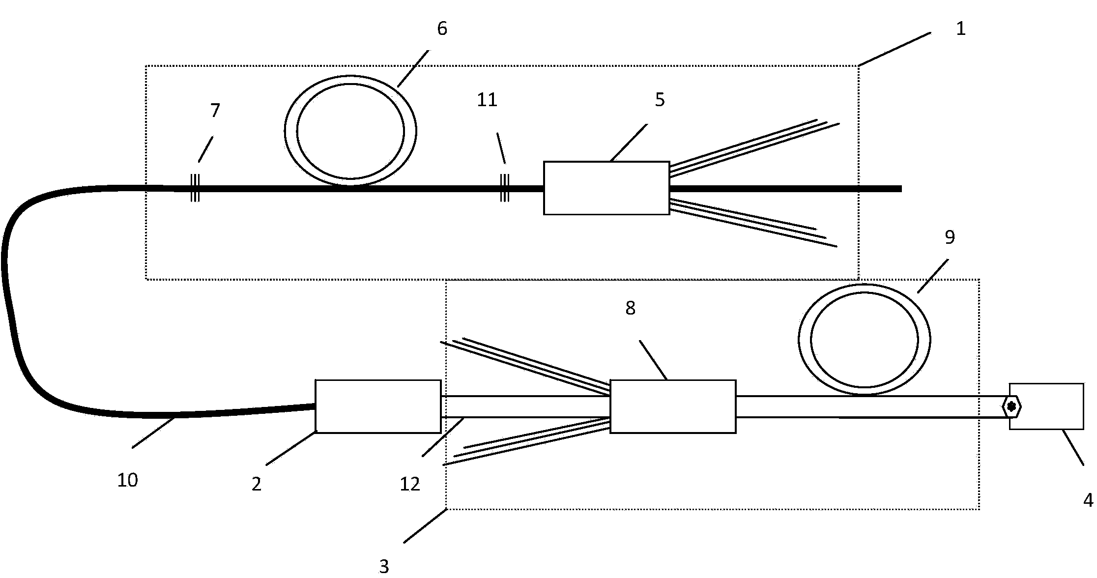
[0025] Such as figure 1 As shown, a high-power multi-core fiber laser is composed of a seed source 1, a mode matcher 2, an amplifier 3, and an optical fiber transmission system. It is characterized in that: the seed source 1 is composed of (N+1)x1 coupler 5 Composed of doped optical fiber 6 and two fiber gratings (7, 11), the output end of (N+1)x1 coupler 5 is connected to a fiber grating 11, doped optical fiber 6, and another fiber grating 7 in sequence, the described Mode matcher 2 is made up of the output fiber 10 of seed source 1 and multicore fiber 12, and described amplifier 3 is made up of multicore (N+1)x1 coupler 8 and multicore doped fiber 9, and mode matcher 2 The multi-core fiber 12 is connected to the input end of the multi-core (N+1)x1 coupler 8, the output end of the multi-core (N+1)x1 coupler 8 is connected to the multi-core doped fiber 9, and the multi-core doped fiber 9 outputs The end cut flat and the end cap 4 are fused to form an optical fiber transmissio...


PUM


Abstract

The invention relates to a high-power multi-core optical fiber laser device. The high-power multi-core optical fiber laser device is composed of a seed resource, a pattern matcher, an amplifier and an optical fiber transmission system. The seed resource is composed of (N+1)*1 couplers, doping optical fibers and two fiber bragging gratings. The output ends of the (N+1)*1 couplers are sequentially connected with one fiber bragging grating, the doping optical fibers and the other fiber bragging grating. The pattern matcher is composed of output optical fibers and multi-core optical fibers of the seed resource and the amplifier is composed of the multi-core (N+1)*1 couplers and the multi-core doping optical fibers. The multi-core optical fibers of the pattern-type matcher are connected with the input ends of the multi-core (N+1)*1 couplers and the output ends of the multi-core (N+1)*1 couplers are connected with the multi-core doping optical fibers. Flattening or tapering flattening is conducted on the output ends of the multi-core doping optical fibers, so that the output ends of the multi-core doping optical fibers are connected with an end cap in a fused mode to form the optical fiber transmission system to output lasers. The high-power multi-core optical fiber laser device can effectively avoid the non-linear phenomenon, enables ultra-high power laser output to be achieved and has the advantages of being compact in structure, high in photoelectric conversion efficiency, stable, reliable and good in laser beam quality.

Description

Technical field: [0001] The invention belongs to the technical field of fiber lasers, and relates to a high-power multi-core fiber laser, which is used to couple a single-channel seed source signal into a multi-core fiber, amplify it through the multi-core fiber, and finally synthesize it into one output, so as to suppress high-power Linearity, to improve the output power of the fiber laser while ensuring the beam quality. technical background: [0002] Fiber lasers are the third generation of new lasers after traditional gas lasers and solid-state lasers. They have the advantages of compact structure, long life, maintenance-free, good beam quality, energy saving and environmental protection, etc., and have been successfully used in mechanical processing, medical treatment, automobile manufacturing and military and other fields. With the continuous expansion of its application fields, such as laser cutting and welding of medium and thick metal plates in industries such as a...

Claims


Application Information

Patent Timeline
Patent Type & Authority Applications(China)
IPC IPC(8): H01S3/067H01S3/08
Inventor 施建宏闫大鹏李成李立波
Owner WUHAN RAYCUS FIBER LASER TECHNOLOGY CO LTD
Learn More