
Flame detection device

A flame detection and detector technology, which is applied in the field of safety monitoring devices, can solve the problems of unsatisfactory sealing performance and the reliability to be improved, and achieves the effect of being beneficial to the service life and accuracy and ensuring the sealing performance.

Active Publication Date: 2014-09-17
SICHUAN TIANWEI ELECTRONICS
View PDF7 Cites 4 Cited by
  • Summary
  • Abstract
  • Description
  • Claims
  • Application Information

AI Technical Summary

Problems solved by technology

[0004] Aiming at the unsatisfactory sealing performance of the flame detector under thermal stress in the above-mentioned prior art, and the reliability needs to be improved in an environment with large temperature difference changes, the present invention provides a flame detection device

Method used


Image

  • Flame detection device

Examples


Embodiment 1

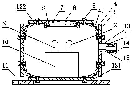
[0027] Such as figure 1 , a flame detection device, comprising a casing in the form of a box and a flame detection assembly arranged in the casing, the casing includes a side wall 3 constituting the side of the casing, a bottom plate 121 constituting the bottom surface of the casing, and a The cover plate 122 and the two flexible connecting rings 4 respectively connecting the side wall 3 and the bottom plate 122, connecting the side wall 3 and the cover plate 121, the flexible connecting ring 4 is annular, and any point on the flexible connecting ring 4 is on the flexible connecting ring 4. The section in the height direction is in the shape of an arc plate; the side wall 3 or the cover plate 122 is also provided with a glass 7 for the passage of light; the flame detection assembly includes any one of the infrared detector 2 or the ultraviolet detector 9 ; The side wall 3 or the cover plate 122 is also provided with a threading pipe 1 for the cable to pass through the shell, a...

Embodiment 2

[0030] The present embodiment is further limited on the basis of embodiment 1, as figure 1 , in order to facilitate the installation and disassembly of the glass 7 on the present invention, to facilitate the assembly and maintenance of the present invention, it also includes a glass fixing seat 8 that is bolted to the side wall 3 or the cover plate 122, and the side wall 3 or the cover plate 122 is provided with a glass clamping groove, and the glass 7 is clamped in the glass clamping groove through the glass fixing seat 8 . The above arrangement makes the glass 7 be detachably connected on the side wall 3 or the cover plate 122 .

Embodiment 3

[0032] The present embodiment is further limited on the basis of embodiment 1, as figure 1 , in order to facilitate the processing, manufacturing and assembly of the present invention, it also includes a plurality of connecting bolts 5, and the flexible connecting ring 4 is connected with the cover plate 122, the bottom plate 121 and the side wall 3 through the connecting bolts 5 and the flexible connecting ring 4. .


PUM


Abstract

The invention discloses a flame detection device. The flame detection device comprises a shell and a flame detection assembly. The shell comprises a side wall, a bottom plate, a cover plate and two flexible connecting rings, wherein the two flexible connecting rings are used for connecting the side wall and the bottom plate and connecting the side wall and the cover plate, the flexible connecting rings are annular, and the cross section of any point on each flexible connecting ring in the height direction of the flexible connecting ring is in the shape of an arc-shaped plate. The side wall or the cover plate is further provided with glass. The flame detection assembly comprises any one of an infrared detector and an ultraviolet detector. The side wall or the cover plate is further provided with a conduit, and the conduit comprises a threaded base, an abutting threaded rod and a sealing ring. The flame detection device is simple in structure, favorable for preventing connection and sealing of the shell from failing under large thermal stress, favorable for the service life and the precision of the flame detection assembly and favorable for guaranteeing the sealing performance of the shell, and the reliability of the flame detection device is improved.

Description

technical field [0001] The invention relates to a safety monitoring device for supervising flame conditions, in particular to a flame detection device. Background technique [0002] At present, there may be flammable gas or dust in places such as chemical plants, oil refineries, substations, industrial warehouses, and even common diesel generator rooms used as emergency power sources. Due to the large number of industrial control equipment and complicated working conditions, these important places must be protected against open flames, Smoke, dust, electrical short circuit, explosion and other sudden abnormal situations are strictly monitored, and flame detection devices are indispensable safety equipment in the above areas. [0003] Flame detection devices in the prior art generally package infrared detectors in aluminum or plastic casings. Depending on the installation position of the flame detectors, the detector circuit may be required to be isolated from the external en...

Claims


Application Information

Patent Timeline
Patent Type & Authority Applications(China)
IPC IPC(8): G01J1/04G08B17/12
Inventor 康美苓姚超杨海燕陈建
Owner SICHUAN TIANWEI ELECTRONICS
Learn More