Liquid crystal grating and manufacturing method thereof

A liquid crystal grating and liquid crystal technology, applied in optics, nonlinear optics, instruments, etc., can solve the problems of phase modulation curve broadening, phase modulation depth reduction, and diffraction efficiency reduction, achieving suppression of fringe electric fields, high resolution, and large The effect of deflection angle

Active Publication Date: 2014-09-10
SOUTHEAST UNIV
View PDF6 Cites 9 Cited by
  • Summary
  • Abstract
  • Description
  • Claims
  • Application Information

AI Technical Summary

Problems solved by technology

This will lead to the broadening of the phase modulation curve and the reduction of the phase modulation depth, such as Figure 4 shown
Finally reflected in the reduction of diffraction efficiency, such as Figure 5 As shown, the diffraction efficiency of the positive and negative orders is less than 10%, while the diffraction efficiency of the zero order exceeds 80%, indicating that most of the incident light cannot be effectively deflected

Method used


Image

  • Liquid crystal grating and manufacturing method thereof
  • Liquid crystal grating and manufacturing method thereof
  • Liquid crystal grating and manufacturing method thereof

Examples


Embodiment Construction

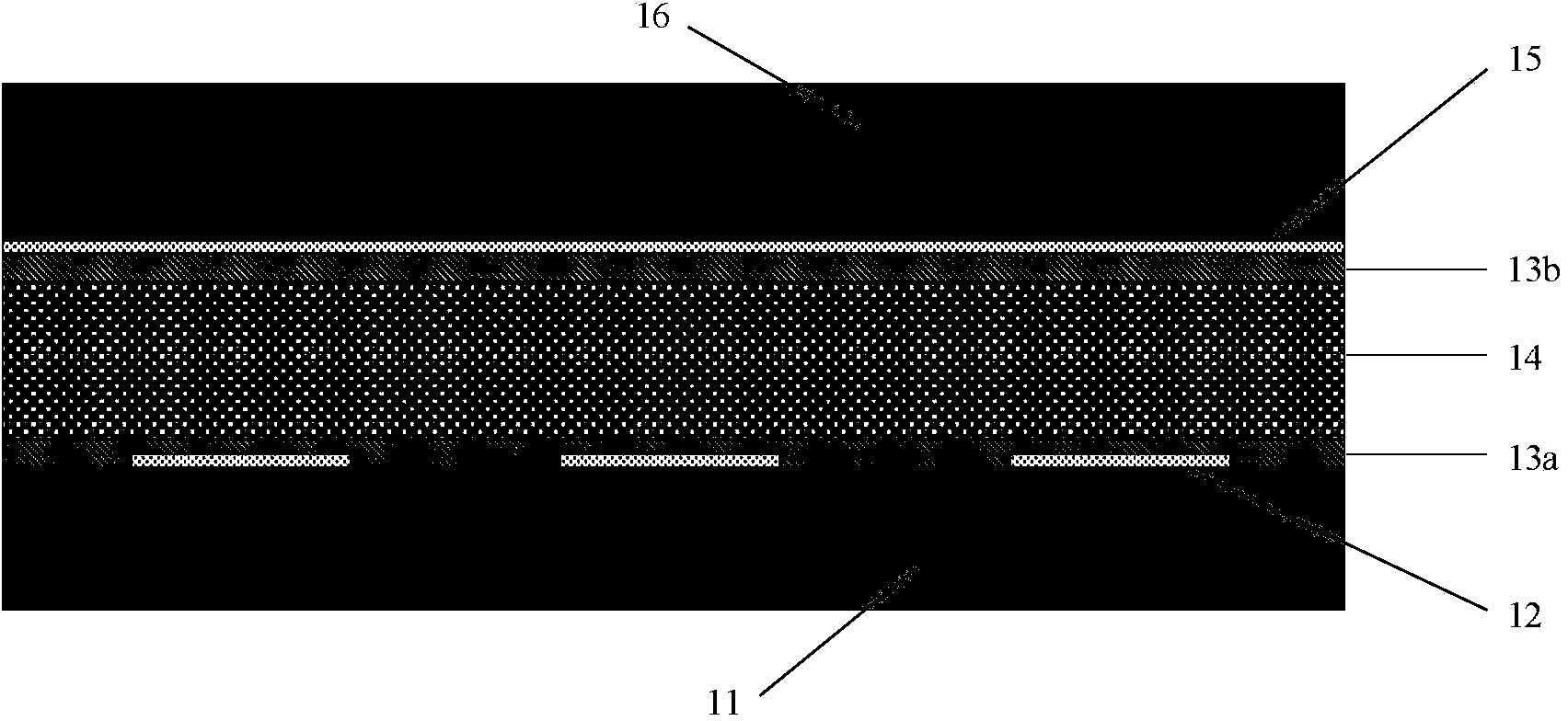
[0042] Figure 6 is a schematic diagram of the cross-sectional structure of the liquid crystal grating of the present invention, such as Figure 6As shown, the present invention proposes a liquid crystal grating, and a liquid crystal 66 is poured between the lower glass substrate 61 and the upper glass substrate 68 . On the lower glass substrate 61, a lower ground electrode 62, an insulating dielectric layer 69a, an address electrode 63, an insulating dielectric layer 69b, an upper ground electrode 64, and a liquid crystal alignment layer 65a are sequentially distributed, and on the upper glass substrate 68, a ground electrode 67 is sequentially distributed. , Liquid crystal alignment layer 65b. In the present invention, indium tin oxide film (ITO) is preferably used as the material of the lower ground electrode 62 , the address electrode 63 , the upper ground electrode 64 , and the ground electrode 67 .

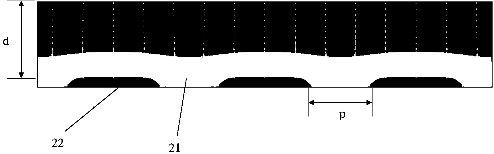
[0043] Figure 7 It is a schematic diagram of the three-dimensional ...


PUM

PropertyMeasurementUnit
thicknessaaaaaaaaaa

Abstract

The invention discloses the structure of a liquid crystal grating. The liquid crystal grating comprises an upper substrate, a lower substrate and liquid crystals, wherein a transparent conducting thin film is arranged on the upper substrate, lower strip-shaped grounding electrode layers are sequentially etched on the lower substrate, a first dielectric layer is deposited on lower grounding electrodes, addressing electrodes which are parallel to the lower grounding electrodes in a staggered mode are formed on the dielectric layer, a second dielectric layer is deposited on the addressing electrodes again, then upper strip-shaped grounding electrodes which are overlapped with the lower grounding electrodes are formed on the second deposited dielectric layer, and the liquid crystals are clamped between the upper substrate and the lower substrate. According to the liquid crystal grating, a transverse electric field between addressing electrodes in a traditional liquid crystal grating and grounding electrodes of an upper glass substrate is effectively restrained through the shielding effect of the upper grounding electrodes and the lower grounding electrodes on the lower glass substrate on an addressing electrode power line, and therefore the edge electric field extending to a non-addressing electrode area is restrained. The structure of the liquid crystal grating can be used for the design of liquid crystal grating with the high resolution and the large deflection angle.

Description

technical field [0001] The invention relates to an optical device, in particular to a liquid crystal grating for suppressing fringe electric field. Background technique [0002] Compared with traditional mechanical devices, liquid crystal gratings have various advantages such as small size, low driving voltage, low power consumption, high resolution, and convenient change of diffraction characteristics, and can be widely used in diffractive optics, spectroscopic measurement, Beam deflection control, optical information processing, optical computing, optical communication and other fields. [0003] The basic device structure of liquid crystal phase grating is as follows: figure 1 As shown: a nematic liquid crystal 14 with dielectric anisotropy is filled between the upper glass substrate 16 and the lower glass substrate 11 to form a liquid crystal cell. A transparent address electrode 12 and a liquid crystal alignment film 13 a are formed on the lower glass substrate 11 , an...

Claims


Application Information

Patent Timeline
Patent Type & Authority Applications(China)
IPC IPC(8): G02F1/1333G02F1/1343G02F1/1337
Inventor 杨磊夏军张晓兵
Owner SOUTHEAST UNIV
Why Eureka
Try Eureka